PyTinyRenderer软渲染器-03
Z-Buffer算法是计算机图形学中常用的一种隐藏面消除(Hidden Surface Removal)的算法。在渲染3D图形时,有些物体会遮挡住其他物体,使得它们在2D视图中不可见。Z-Buffer算法就是用来确定哪些物体在视图中是可见的,哪些是被遮挡的。上一节中我们虽然渲染出了模型,但是嘴唇凹进去的阴影面缺显示在上层,本次就拿Z-Buffer算法来处理这个问题。
Z-Buffer算法与画家算法
首先想想为什么需要Z-Buffer算法?或者说Z-Buffer算法究竟解决了什么问题?
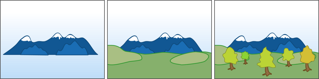
理论上,我们可以绘制所有的三角形。如果我们按照正确的顺序从后向前绘制,那么前面的面片将覆盖后面的面片。这种方法被称为画家算法。就如下图,你要先画山、再画草坪、再画树,这就是画家算法的最直观的原理呈现:
然而,这种方法的计算成本非常高:每次摄像机移动,我们都需要重新对整个场景进行排序。对于动态场景,这种需求更是复杂。然而,这甚至不是最主要的问题,最主要的问题在于确定正确的绘制顺序并不是固定不变的。
TinyRenderer给出了样例图你可以参考着想象一下,想象一个由三个三角形组成的简单场景: 相机向上向下看,我们将彩色的三角形投射到白色屏幕上,染出来的结果应该像右边这样:
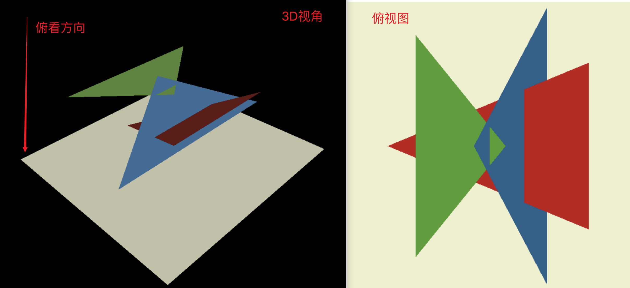
确定蓝色面是位于红色面的前方还是后方?我们发现在这种情况下,画家算法无法给出答案。一种可能的解决方案是将蓝色面分割成两部分,一部分在红色面前,一部分在红色面后。然后再将红色三角形前的部分进一步分割,一部分在绿色三角形前,一部分在绿色三角形后…… 我们可以看到这个问题的复杂性:在包含数百万个三角形的场景中,这样的计算会变得极其繁琐。
我发现TinyRenderer的作者作为一名老师是非常敬业的,很讲究教学方法,这里他提供了一个重要的思想就是降维。
降低一个维度思考问题
暂时丢弃一个维度,沿着黄色平面剪掉上面的场景,此时我们需要考虑的就只有中间这条线的颜色如何填充即可:
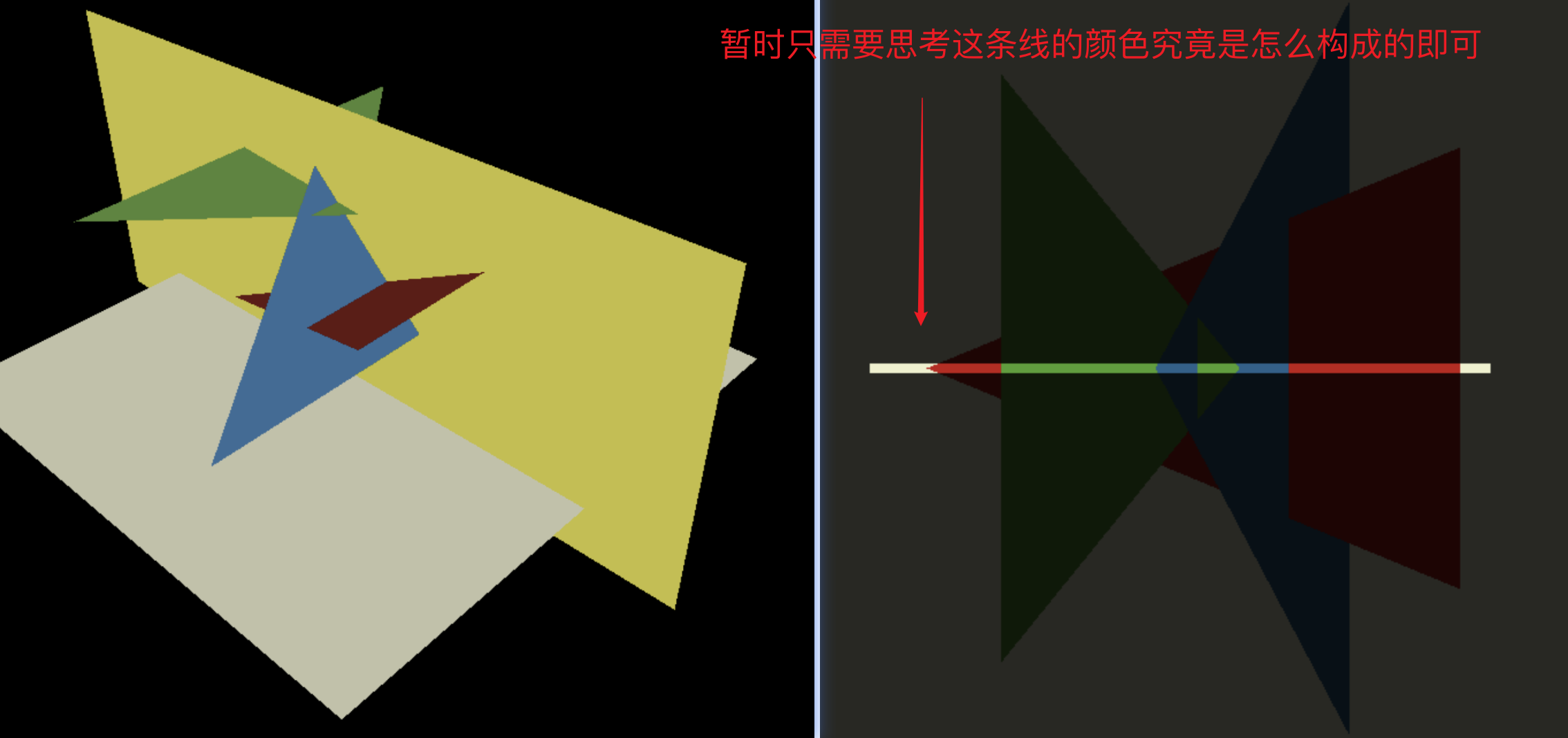
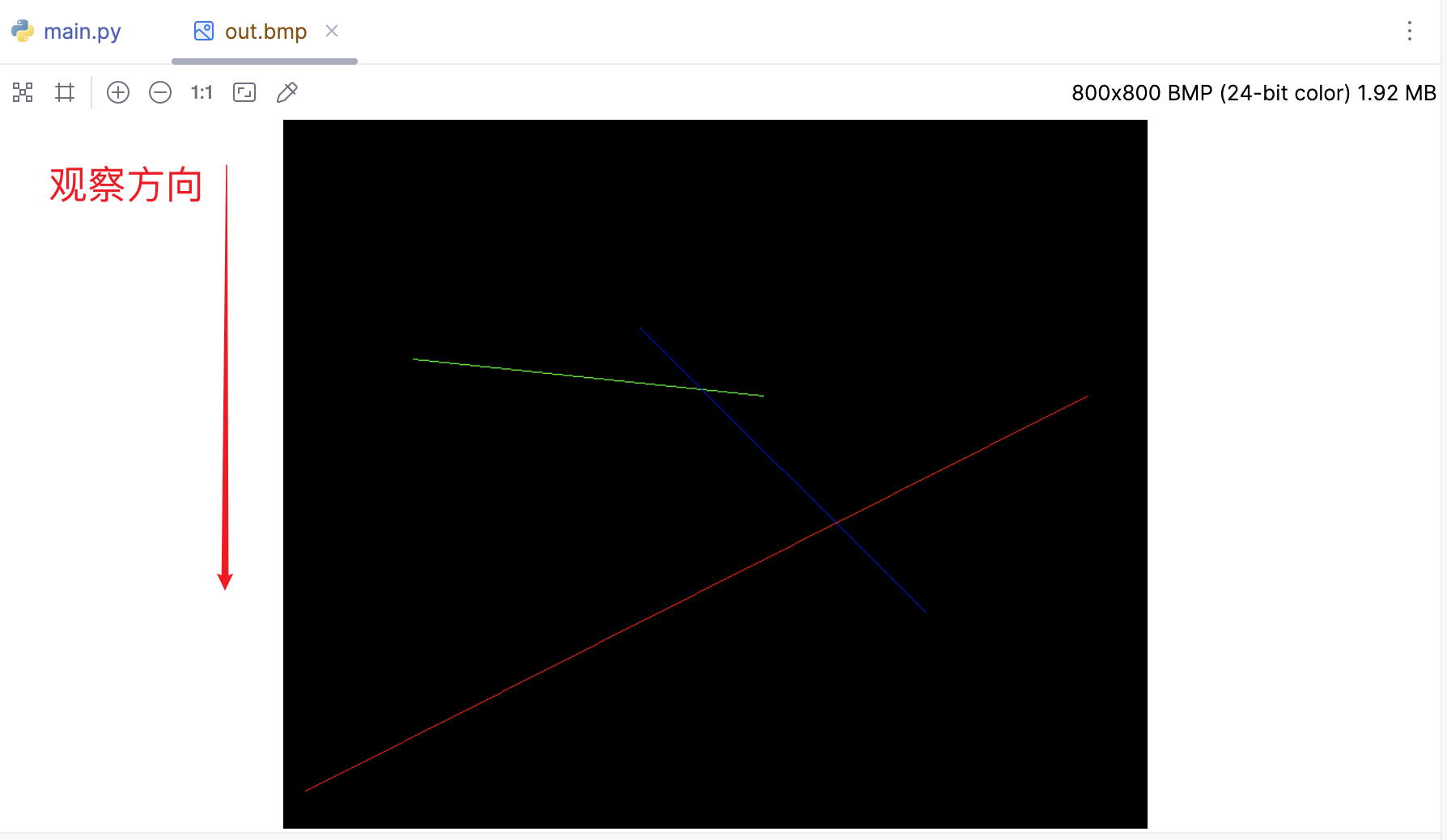
针对这三个三角形,我们先绘制一个2D侧视图,其实也能看出来如果我们从上往下看,也就是图中的观察方向,看到的颜色条应该是:黑、红、绿、蓝、绿、蓝、红、黑这样的顺序排列。我们要做的无非就是把我们大脑思考的过程转化为代码即可,先绘图:
if __name__ == '__main__':
    width = 800
    height = 800
    image = MyImage((width, height))

    line(20, 34, 744, 400, image, red)
    line(120, 434, 444, 400, image, green)
    line(330, 463, 594, 200, image, blue)

    image.save('out.bmp')
创建了一个维度为 (width, 1) 的数组 y-buffer,这个数组的元素均用负无穷整数初始化。随后调用了 rasterize() 函数,将这个渲染对象作为参数传入。为了方便观察,创建64个像素高度的Image:
def rasterize(p0: Vec2, p1: Vec2, img: MyImage, y_img: MyImage, color, buffer):
    if p0.x > p1.x:
        p0, p1 = p1, p0
    for x in range(p0.x, p1.x + 1):
        _x = p1.x - p0.x
        if _x == 0:
            continue
        # 计算线性插值的参数
        t = (x - p0.x) / _x
        # 对 y 值进行线性插值
        y = int(p0.y * (1 - t) + p1.y * t)
        # 如果当前像素的 y 值大于 buffer 中存储的 y 值(表示更靠近观察者)
        if buffer[x] < y:
            buffer[x] = y
            depth_color = int(y / 462 * 255)
            for h in range(0, 64):
                img.putpixel((x, h), color)
                y_img.putpixel((x, h), (depth_color, depth_color, depth_color))


if __name__ == '__main__':
    width = 800
    height = 64
    image = MyImage((width, height))
    y_image = MyImage((width, height))

    # -sys.maxsize - 1 最小值
    y_buffer = [-sys.maxsize - 1] * width

    rasterize(Vec2([20, 34]), Vec2([744, 400]), image, y_image, red, y_buffer)
    rasterize(Vec2([120, 434]), Vec2([444, 400]), image, y_image, green, y_buffer)
    rasterize(Vec2([330, 463]), Vec2([594, 200]), image, y_image, blue, y_buffer)

    image.save('out.bmp')
    y_image.save('y_out.bmp')
简单复习下线性插值的基本原理:在这个场景中,我们已知线段的两个端点(p0和p1),我们想要找到线段上任何一个点的位置。假设我们有两个点 $p0(x_0, y_0)$ 和 $p1(x_1, y_1)$,我们想要找到在这两点连线上的某一点 $P(x, y)$。假设 $P$ 与 $p0$ 在x轴上的距离占整个线段在x轴上的距离的比例是 $t$,那么我们可以计算出 $P$ 的坐标:
$$ x = x_0 + t * (x_1 - x_0) $$ $$ y = y_0 + t * (y_1 - y_0) $$
在这个代码中,我们已经知道了 $x$ 的值(就是我们正在遍历的像素的x坐标),我们的目标是找到对应的 $y$ 值。因此我们可以先计算出 $t$
$$ t = \frac{x - x_0}{x_1 - x_0} $$
然后用 $t$ 来计算 $y$:
$$ y = y_0 * (1 - t) + y_1 * t $$
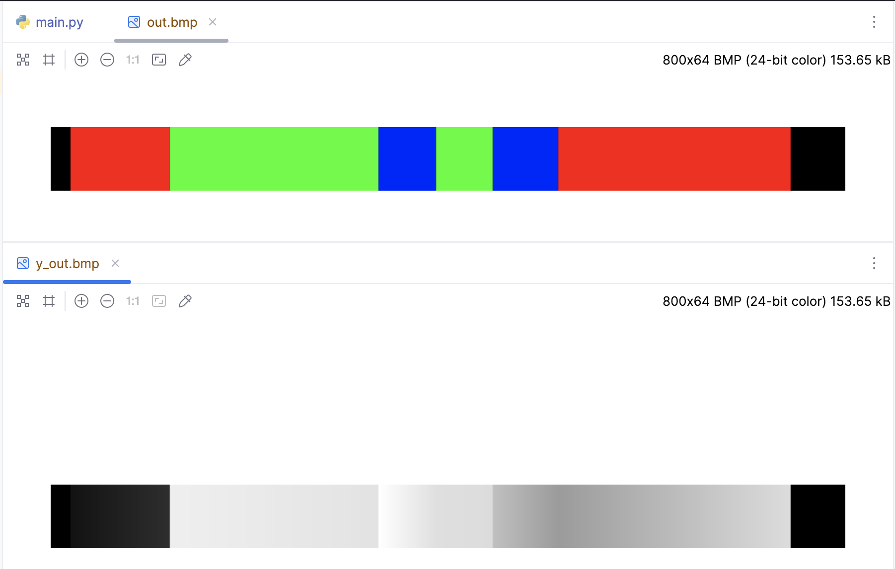
跟我们预想的黑、红、绿、蓝、绿、蓝、红、黑这样的顺序排列完全一样,而且顺便绘制了y-buffer深度图,颜色越深表示离观察点越远,回想看看上面的侧视图,的确是这样吧,现在让开始回归到3D的场景来思考Z-Buffer算法。
3D场景的Z-Buffer算法
对于二维的情况来说,我们需要Y-Buffer,对于3D场景也是同样的道理,我们需要一个二维数组来作为深度缓冲区。由于二维数组本质上也是个普通数组,所以直接采用如下的方式进行初始化:
z_buffer = [-sys.maxsize - 1] * width * height

# index、xy之间互相转化也比较方便
index = x + y * width
x = idx % width
y = int(idx / width)
下面是完整的代码:
def triangle(p0: Vec3, p1: Vec3, p2: Vec3, img: MyImage, z_img: MyImage, color):
min_x = max(0, min(p0.x, p1.x, p2.x))
max_x = min(img.width - 1, max(p0.x, p1.x, p2.x))
min_y = max(0, min(p0.y, p1.y, p2.y))
max_y = min(img.height - 1, max(p0.y, p1.y, p2.y))
P = Vec2((0, 0))
# 遍历包围盒内的每个像素
for P.y in range(min_y, max_y+1):
for P.x in range(min_x, max_x+1):
# 计算当前像素的重心坐标
bc_screen = barycentric(p0, p1, p2, P)
if bc_screen is None:
continue
# 如果像素的重心坐标的任何一个分量小于0,那么这个像素就在三角形的外部,我们就跳过它
if bc_screen.x < 0 or bc_screen.y < 0 or bc_screen.z < 0:
continue
# 计算当前像素的深度
z = p0.z * bc_screen.x + p1.z * bc_screen.y + p2.z * bc_screen.z
# 检查Z缓冲区,如果当前像素的深度比Z缓冲区中的值更近,那么就更新Z缓冲区的值,并绘制像素
idx = P.x + P.y * img.width
if z_buffer[idx] < z:
z_buffer[idx] = z
image.putpixel((P.x, P.y), color)
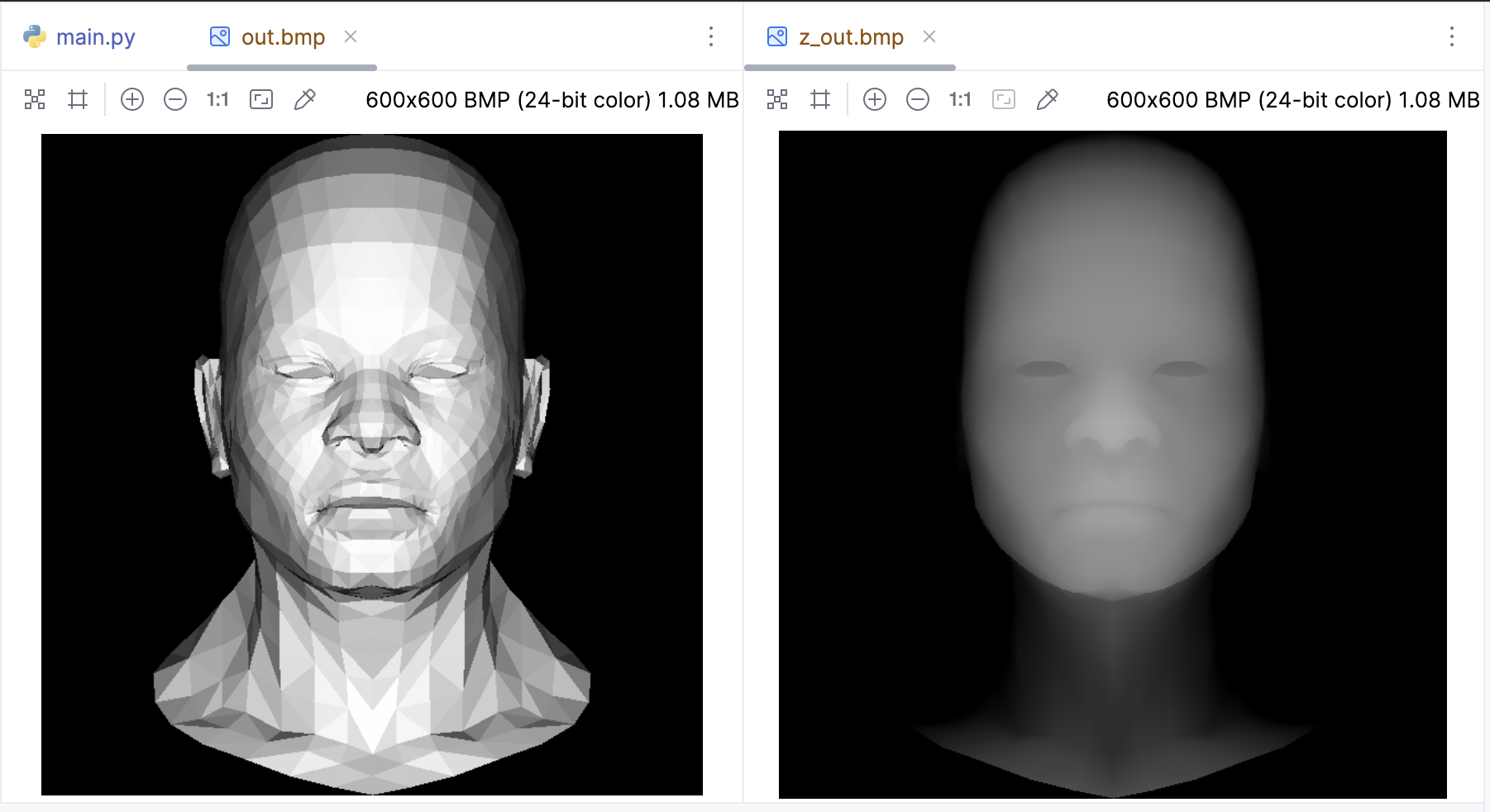
# 绘制深度图z_img
depth_color = int(z * 255)
if depth_color > 0:
z_img.putpixel((P.x, P.y), (depth_color, depth_color, depth_color))
if __name__ == '__main__':
width = 600
height = 600
image = MyImage((width, height))
# 深度缓冲展示一下
z_image = MyImage((width, height))
# -sys.maxsize - 1 最小值
z_buffer = [-sys.maxsize - 1] * width * height
obj = OBJFile('african_head.obj')
obj.parse()
light_dir = Vec3([0, 0, -1])
for face in obj.faces:
screen_coords = []
world_coords = [None, None, None]
for j in range(3):
v: Vec3 = obj.vert(face[j])
screen_coords.append(Vec3([int((v.x + 1) * width / 2), int((v.y + 1) * height / 2), v.z]))
world_coords[j] = v
# 计算三角形的法向量和光照强度
n: Vec3 = (world_coords[2] - world_coords[0]).cross(world_coords[1] - world_coords[0])
n.normalize()
intensity = n * light_dir
# 负的就剔除掉
if intensity > 0:
triangle(screen_coords[0], screen_coords[1], screen_coords[2], image, z_image,
(int(255 * intensity), int(255 * intensity), int(255 * intensity)))
image.save('out.bmp')
z_image.save('z_out.bmp')
纹理坐标插值
到目前为止,我们渲染的模型都是白模,如何把纹理贴上去呢?
这里有必要复习一下OBJ文件的格式,还记得OBJ文件中的vt吗? vt:这是一个纹理坐标。它通常是一个二维坐标,表示为(u, v),用于映射3D模型的表面纹理。例如,vt 0.500 1.000表示一个纹理坐标位于(0.5,1),所以Z坐标通常都是0。所以需要对之前的OBJ文件读取的类稍加修改:
from vector import Vec3


class OBJFile:
    def __init__(self, filename):
        self.filename = filename
        self.vertices = []
        self.texture_coords = []  # 添加一个新的列表来存储纹理坐标
        self.faces = []

    def parse(self):
        with open(self.filename, 'r') as file:
            for line in file:
                components = line.strip().split()
                if len(components) > 0:
                    if components[0] == 'v':
                        self.vertices.append([float(coord) for coord in components[1:]])
                    elif components[0] == 'vt':  # 添加一个新的条件来处理纹理坐标
                        self.texture_coords.append([float(coord) for coord in components[1:]])
                    elif components[0] == 'f':
                        # 修改这里,以便同时存储顶点和纹理坐标的索引
                        self.faces.append([[int(index.split('/')[0]),
                                            int(index.split('/')[1])] for index in components[1:]])

    def vert(self, i):
        """
        :param i: vertex index
        :param i: 因为obj文件的顶点索引是从1开始的,所以需要减1
        :return:
        """
        return Vec3(self.vertices[i - 1])

    def texcoord(self, i):  # 添加一个新的方法来获取纹理坐标
        """
        :param i: texture coordinate index
        :param i: 因为obj文件的纹理坐标索引是从1开始的,所以需要减1
        :return:
        """
        return Vec3(self.texture_coords[i - 1])
开始贴图,african_head_diffuse.tga 是一个压缩的TGA文件,这里直接使用pillow来读取:
from PIL import Image

if __name__ == '__main__':
    width = 600
    height = 600

    tga: Image = Image.open('african_head_diffuse.tga')

    image = MyImage((width, height))

    # -sys.maxsize - 1 最小值
    z_buffer = [-sys.maxsize - 1] * width * height

    obj = OBJFile('african_head.obj')
    obj.parse()

    light_dir = Vec3([0, 0, -1])
    for face in obj.faces:
        screen_coords = []
        world_coords = [None, None, None]
        uv_coords = [None, None, None]
        for j in range(3):
            v: Vec3 = obj.vert(face[j][0])
            screen_coords.append(Vec3([int((v.x + 1) * width / 2), int((v.y + 1) * height / 2), v.z]))
            world_coords[j] = v
            uv_coords[j] = obj.texcoord(face[j][1])  # 获取纹理坐标

        # 计算三角形的法向量和光照强度
        n: Vec3 = (world_coords[2] - world_coords[0]).cross(world_coords[1] - world_coords[0])
        n.normalize()
        intensity = n * light_dir
        # 负的就剔除掉
        if intensity > 0:
            color = tga.getpixel((int(uv_coords[0].x * tga.width), int(uv_coords[0].y * tga.height)))
            color = (int(color[0] * intensity), int(color[1] * intensity), int(color[2] * intensity))

            triangle(screen_coords[0], screen_coords[1], screen_coords[2], image, color)

    image.save('out.bmp')
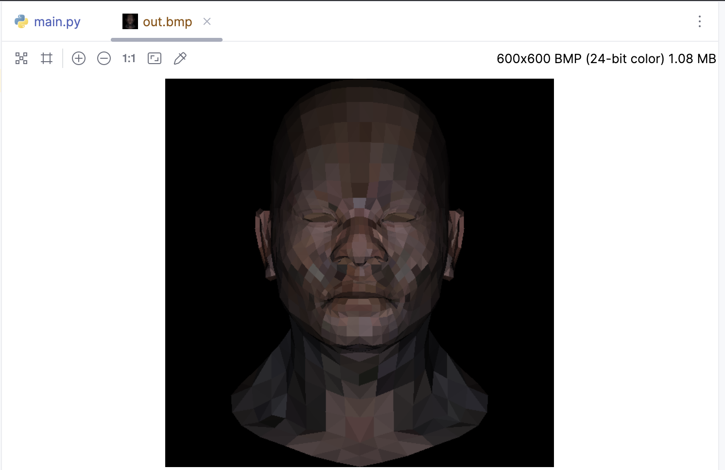
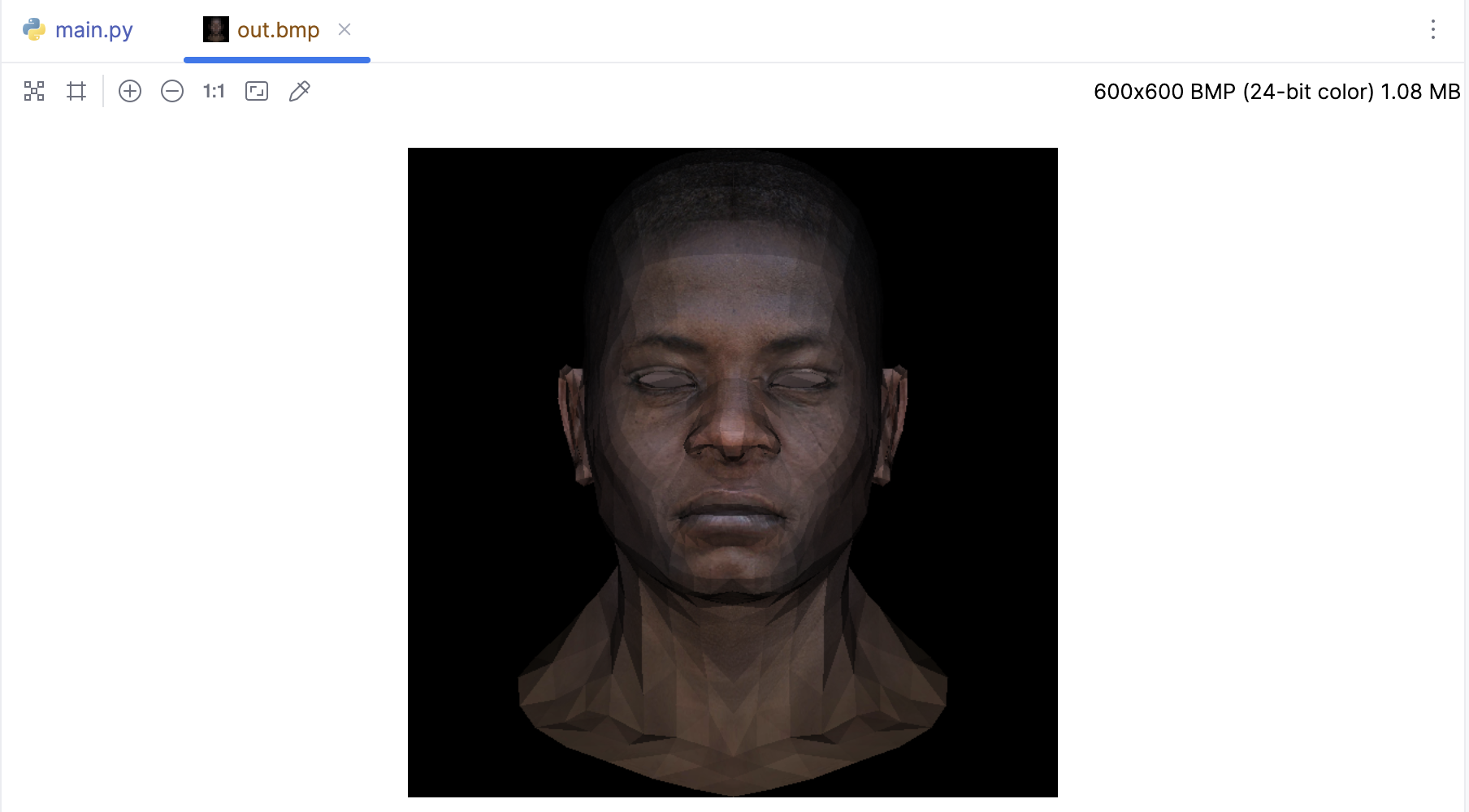
我们使用了第一个顶点的纹理坐标来获取颜色,而不是使用所有顶点的纹理坐标来插值颜色。所以模型可能会看起来有些奇怪,因为所有的颜色都是从第一个顶点的纹理坐标开始的。如果我们想要更准确的颜色,需要在 triangle 函数中插值纹理坐标:
def triangle(p0: Vec3, p1: Vec3, p2: Vec3,
             uv0: Vec2, uv1: Vec2, uv2: Vec2,
             intensity, img: MyImage, tga: Image):
    min_x = max(0, min(p0.x, p1.x, p2.x))
    max_x = min(img.width - 1, max(p0.x, p1.x, p2.x))
    min_y = max(0, min(p0.y, p1.y, p2.y))
    max_y = min(img.height - 1, max(p0.y, p1.y, p2.y))
    P = Vec2((0, 0))
    # 遍历包围盒内的每个像素
    for P.y in range(min_y, max_y+1):
        for P.x in range(min_x, max_x+1):
            # 计算当前像素的重心坐标
            bc_screen = barycentric(p0, p1, p2, P)
            if bc_screen is None:
                continue
            # 如果像素的重心坐标的任何一个分量小于0,那么这个像素就在三角形的外部,我们就跳过它
            if bc_screen.x < 0 or bc_screen.y < 0 or bc_screen.z < 0:
                continue

            # 使用重心坐标来插值纹理坐标
            uv = uv0 * bc_screen.x + uv1 * bc_screen.y + uv2 * bc_screen.z
            # 使用插值后的纹理坐标来从TGA文件中获取颜色
            # 此TGA文件是从左上角开始的,所以需要将纵坐标反转
            color = tga.getpixel((int(uv.x * tga.width), tga.height - 1 - int(uv.y * tga.height)))
            color = (int(color[0] * intensity), int(color[1] * intensity), int(color[2] * intensity))

            # 计算当前像素的深度
            z = p0.z * bc_screen.x + p1.z * bc_screen.y + p2.z * bc_screen.z

            # 检查Z缓冲区,如果当前像素的深度比Z缓冲区中的值更近,那么就更新Z缓冲区的值,并绘制像素
            idx = P.x + P.y * img.width
            if z_buffer[idx] < z:
                z_buffer[idx] = z
                image.putpixel((P.x, P.y), color)


def world2screen(v: Vec3) -> Vec3:
    return Vec3([int((v.x + 1.) * width/2. + .5), int((v.y + 1.) * height/2. + .5), v.z])


if __name__ == '__main__':
    width = 600
    height = 600

    tga: Image = Image.open('african_head_diffuse.tga')

    image = MyImage((width, height))

    # -sys.maxsize - 1 最小值
    z_buffer = [-sys.maxsize - 1] * width * height

    obj = OBJFile('african_head.obj')
    obj.parse()

    light_dir = Vec3([0, 0, -1])
    for face in obj.faces:
        screen_coords = []
        world_coords = [None, None, None]
        uv_coords = [None, None, None]
        for j in range(3):
            v: Vec3 = obj.vert(face[j][0])
            screen_coords.append(Vec3([int((v.x + 1) * width / 2), int((v.y + 1) * height / 2), v.z]))
            world_coords[j] = v
            uv_coords[j] = obj.texcoord(face[j][1])  # 获取纹理坐标

        # 计算三角形的法向量和光照强度
        n: Vec3 = (world_coords[2] - world_coords[0]).cross(world_coords[1] - world_coords[0])
        n.normalize()
        intensity = n * light_dir
        # 负的就剔除掉
        if intensity > 0:
            triangle(screen_coords[0], screen_coords[1], screen_coords[2],
                     uv_coords[0], uv_coords[1], uv_coords[2],
                     intensity, image, tga)

    image.save('out.bmp')
完整代码:
import sys
from PIL import Image
from image import MyImage
from obj import OBJFile
from vector import Vec3, Vec2

white = (255, 255, 255)
red = (255, 0, 0)
green = (0, 255, 0)
blue = (0, 0, 255)


def triangle_area_2d(a: Vec2, b: Vec2, c: Vec2) -> float:
    """
    计算三角形面积
    """
    return .5 * ((b.y - a.y) * (b.x + a.x) + (c.y - b.y) * (c.x + b.x) + (a.y - c.y) * (a.x + c.x))


def barycentric(A, B, C, P):
    """
    计算重心坐标 u, v, w
    """
    total_area = triangle_area_2d(A, B, C)
    if total_area == 0:
        return None  # 或者抛出一个异常,或者返回一个特殊的值
    u = triangle_area_2d(P, B, C) / total_area
    v = triangle_area_2d(P, C, A) / total_area
    w = triangle_area_2d(P, A, B) / total_area
    return Vec3([u, v, w])


def triangle(p0: Vec3, p1: Vec3, p2: Vec3,
             uv0: Vec2, uv1: Vec2, uv2: Vec2,
             intensity, img: MyImage, tga: Image):
    min_x = max(0, min(p0.x, p1.x, p2.x))
    max_x = min(img.width - 1, max(p0.x, p1.x, p2.x))
    min_y = max(0, min(p0.y, p1.y, p2.y))
    max_y = min(img.height - 1, max(p0.y, p1.y, p2.y))
    P = Vec2((0, 0))
    # 遍历包围盒内的每个像素
    for P.y in range(min_y, max_y+1):
        for P.x in range(min_x, max_x+1):
            # 计算当前像素的重心坐标
            bc_screen = barycentric(p0, p1, p2, P)
            if bc_screen is None:
                continue
            # 如果像素的重心坐标的任何一个分量小于0,那么这个像素就在三角形的外部,我们就跳过它
            if bc_screen.x < 0 or bc_screen.y < 0 or bc_screen.z < 0:
                continue

            # 使用重心坐标来插值纹理坐标
            uv = uv0 * bc_screen.x + uv1 * bc_screen.y + uv2 * bc_screen.z
            # 纹理采样:使用插值后的纹理坐标来从TGA文件中获取颜色
            # 此TGA文件是从左上角开始的,所以需要将纵坐标反转
            color = tga.getpixel((int(uv.x * tga.width), tga.height - 1 - int(uv.y * tga.height)))
            color = (int(color[0] * intensity), int(color[1] * intensity), int(color[2] * intensity))

            # 计算当前像素的深度
            z = p0.z * bc_screen.x + p1.z * bc_screen.y + p2.z * bc_screen.z

            # 检查Z缓冲区,如果当前像素的深度比Z缓冲区中的值更近,那么就更新Z缓冲区的值,并绘制像素
            idx = P.x + P.y * img.width
            if z_buffer[idx] < z:
                z_buffer[idx] = z
                image.putpixel((P.x, P.y), color)


if __name__ == '__main__':
    width = 600
    height = 600

    tga: Image = Image.open('african_head_diffuse.tga')

    image = MyImage((width, height))

    # -sys.maxsize - 1 最小值
    z_buffer = [-sys.maxsize - 1] * width * height

    obj = OBJFile('african_head.obj')
    obj.parse()

    light_dir = Vec3([0, 0, -1])
    gamma = 2.2
    for face in obj.faces:
        screen_coords = []
        world_coords = [None, None, None]
        uv_coords = [None, None, None]
        for j in range(3):
            v: Vec3 = obj.vert(face[j][0])
            screen_coords.append(Vec3([int((v.x + 1) * width / 2), int((v.y + 1) * height / 2), v.z]))
            world_coords[j] = v
            uv_coords[j] = obj.texcoord(face[j][1])  # 获取纹理坐标

        # 计算三角形的法向量和光照强度
        n: Vec3 = (world_coords[2] - world_coords[0]).cross(world_coords[1] - world_coords[0])
        n.normalize()
        intensity = n * light_dir
        # 负的就剔除掉
        if intensity > 0:
          	# 带上Gamma校正
            intensity = intensity ** (1 / gamma)
            triangle(screen_coords[0], screen_coords[1], screen_coords[2],
                     uv_coords[0], uv_coords[1], uv_coords[2],
                     intensity, image, tga)

    image.save('out_gamma.bmp')
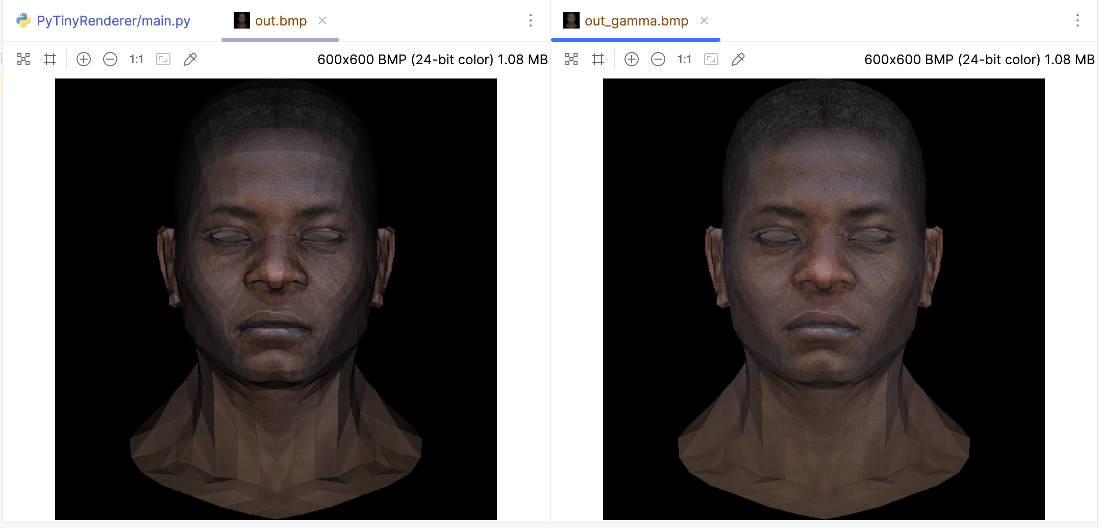
带上Gamma校正后渲染出来的效果很显然看起来更自然:
纹理坐标插值的核心流程:
- 读取纹理坐标:首先,对于每个顶点,我们需要定义一个纹理坐标(通常称为 (u, v) 。这些坐标定义了每个顶点在纹理图像中的位置。在一个三角形中,我们会定义三个这样的坐标。
- 插值计算:对于在三角形内部的每个像素,我们需要知道它在纹理图像中的对应位置。我们可以通过对三个顶点的纹理坐标进行插值来得到这个信息。这个插值过程通常是基于像素到三角形顶点的距离的。我们这里插值过程使用了重心坐标。重心坐标即三角形内部的一个点相对于三角形三个顶点的权重。如果我们知道一个点的重心坐标,我们就可以通过将每个顶点的纹理坐标与对应的权重相乘,然后将结果相加,来得到这个点的纹理坐标。
- 纹理采样:一旦我们有了像素的纹理坐标,就可以从纹理采样样,代码中
tga.getpixel就是在进行纹理采样。 - 像素着色:最后,我们使用从纹理图像中取样得到的颜色来着色像素。光照计算这些都是在纹理坐标插值之后进行的。
到目前为止,我们已经成功地把纹理贴在了模型上,而且通过使用重心坐标来插值纹理坐标,直接就获得了我们期望的效果,而且通过Z-Buffer算法已经很完美的处理了嘴唇凹进去的阴影面缺显示在上层的问题。
本节就先这样,代码我放在这里了: https://github.com/zouchanglin/PyTinyRenderer