PyTinyRenderer软渲染器-02
本节是PyTinyRenderer的第二节,可以把本系列的文章看成是PyTinyRenderer的工程介绍文档,而不是TinyRenderer的Wiki翻译,其实尝试过翻译,但是我发现有时候翻译并不能清晰地表达我的想法,尤其是一些代码上的细节问题,对照原本的C++工程要复现的话需要做很多工作,所以本系列的核心目的也是能够让读者能轻易的复现TinyRenderer这个工程。本节主要实现的部分是三角形光栅化、涉及平面着色、光照模型与背面剔除。
三角形的光栅化
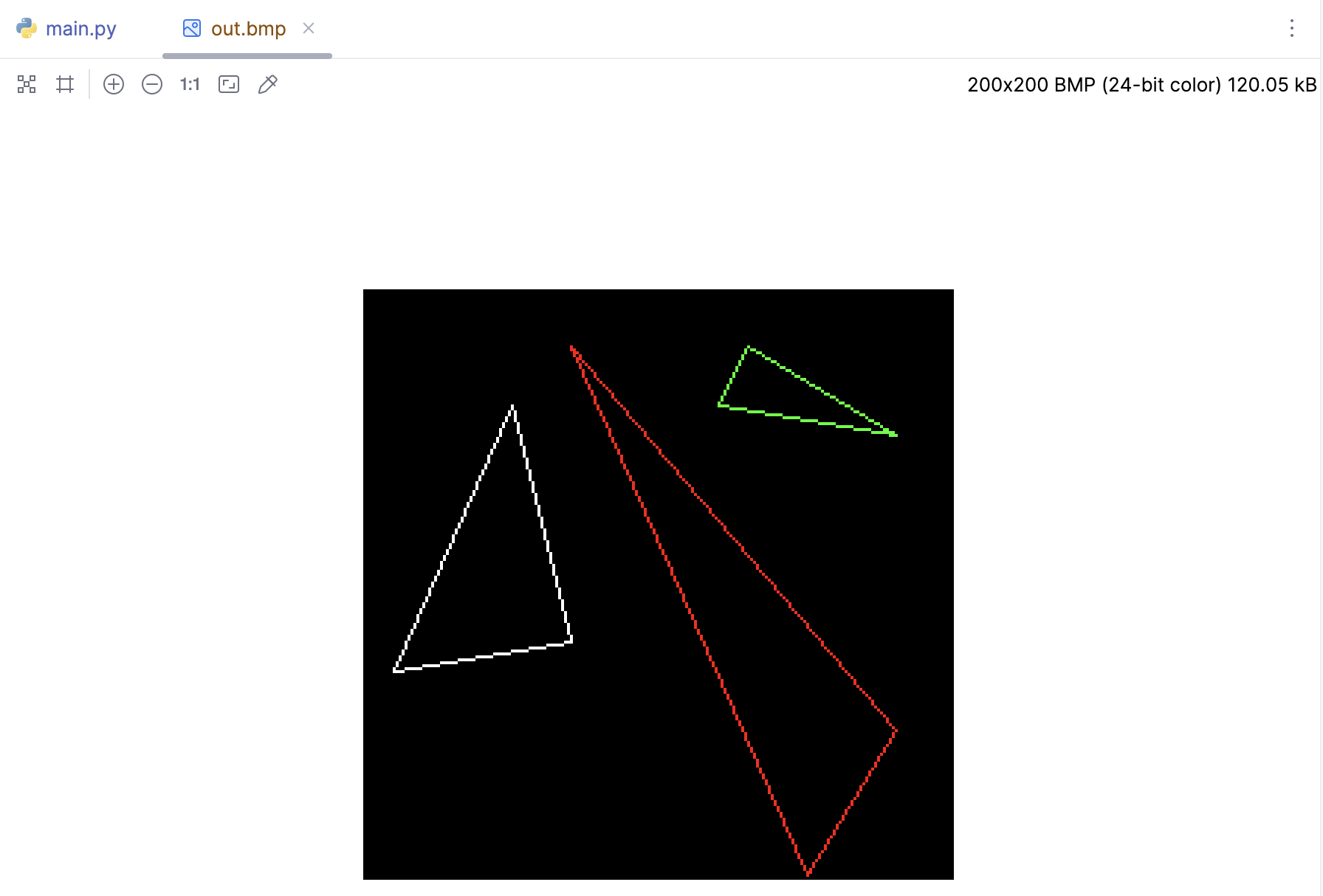
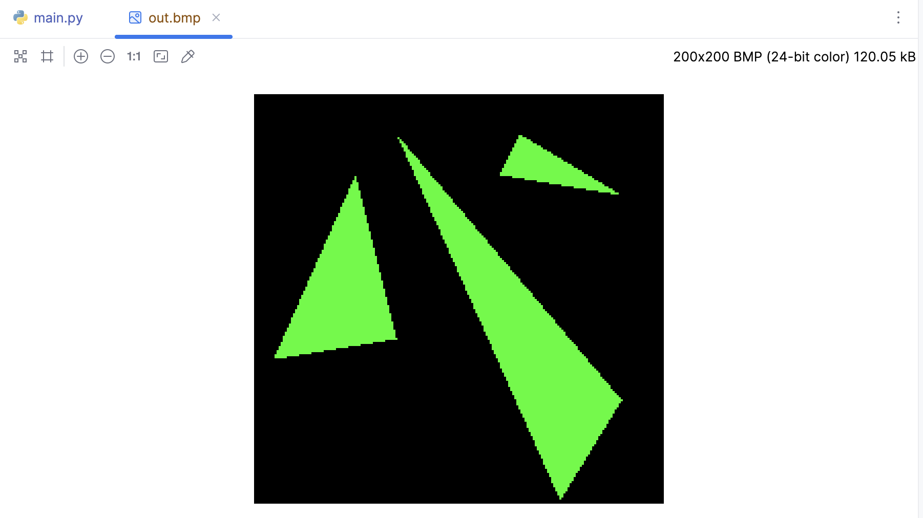
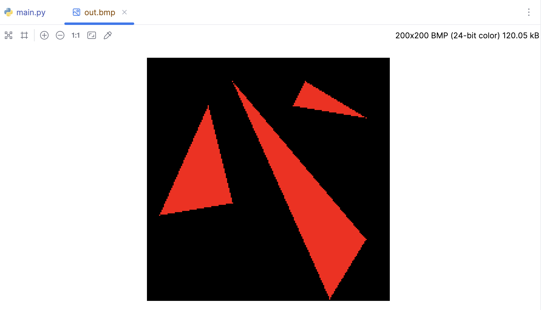
暂时可以先不管三角形的光栅化的概念,我们先来看看如何绘制一个三角形。基于第一节的内容,我们很容易绘制出一个三角形,下面是TinyRenderer的Wiki的三个三角形,我直接拿过来了:
def triangle(p1: Vec2, p2: Vec2, p3: Vec2, img: MyImage, color):
    line(p1.x, p1.y, p2.x, p2.y, img, color)
    line(p1.x, p1.y, p3.x, p3.y, img, color)
    line(p2.x, p2.y, p3.x, p3.y, img, color)


if __name__ == '__main__':
    width = 200
    height = 200
    image = MyImage((width, height))
    white = (255, 255, 255)
    red = (255, 0, 0)
    green = (0, 255, 0)
    obj = OBJFile('african_head.obj')
    obj.parse()

    # 三角形三个顶点
    t1 = [Vec2([10, 70]), Vec2([50, 160]), Vec2([70, 80])]
    t2 = [Vec2([180, 50]), Vec2([150, 1]), Vec2([70, 180])]
    t3 = [Vec2([180, 150]), Vec2([120, 160]), Vec2([130, 180])]
    triangle(t1[0], t1[1], t1[2], image, white)
    triangle(t2[0], t2[1], t2[2], image, red)
    triangle(t3[0], t3[1], t3[2], image, green)

    image.save('out.bmp')
一个绘制三角形的算法应该包括以下功能:
简单高效,非常快速的就可以绘制完成。
应该具有对称性:图片的绘制结果,不应受传递给绘制函数的顶点的顺序影响。
如果两个三角形有两个共同的顶点,其实就是这两个三角形在渲染或绘制时,应该紧密相连,没有间隙。
逐行扫线算法
我们可能会提出更多的需求,但可以先做一个出来简单版本。使用传统的扫线方式:
假设某个三角形的三个顶点:p0、p1、p2,按 y 坐标排序,A(红色)、B(绿色)边分别由 p0-p2、p0-p1构成,并且位于p1 p2之间。
white = (255, 255, 255)
red = (255, 0, 0)
green = (0, 255, 0)

def triangle(p0: Vec2, p1: Vec2, p2: Vec2, img: MyImage):
    if p0.y > p1.y:
        p0, p1 = p1, p0
    if p0.y > p2.y:
        p0, p2 = p2, p0
    if p1.y > p2.y:
        p1, p2 = p2, p1
    line(p0.x, p0.y, p1.x, p1.y, img, green)
    line(p1.x, p1.y, p2.x, p2.y, img, green)
    line(p2.x, p2.y, p0.x, p0.y, img, red)
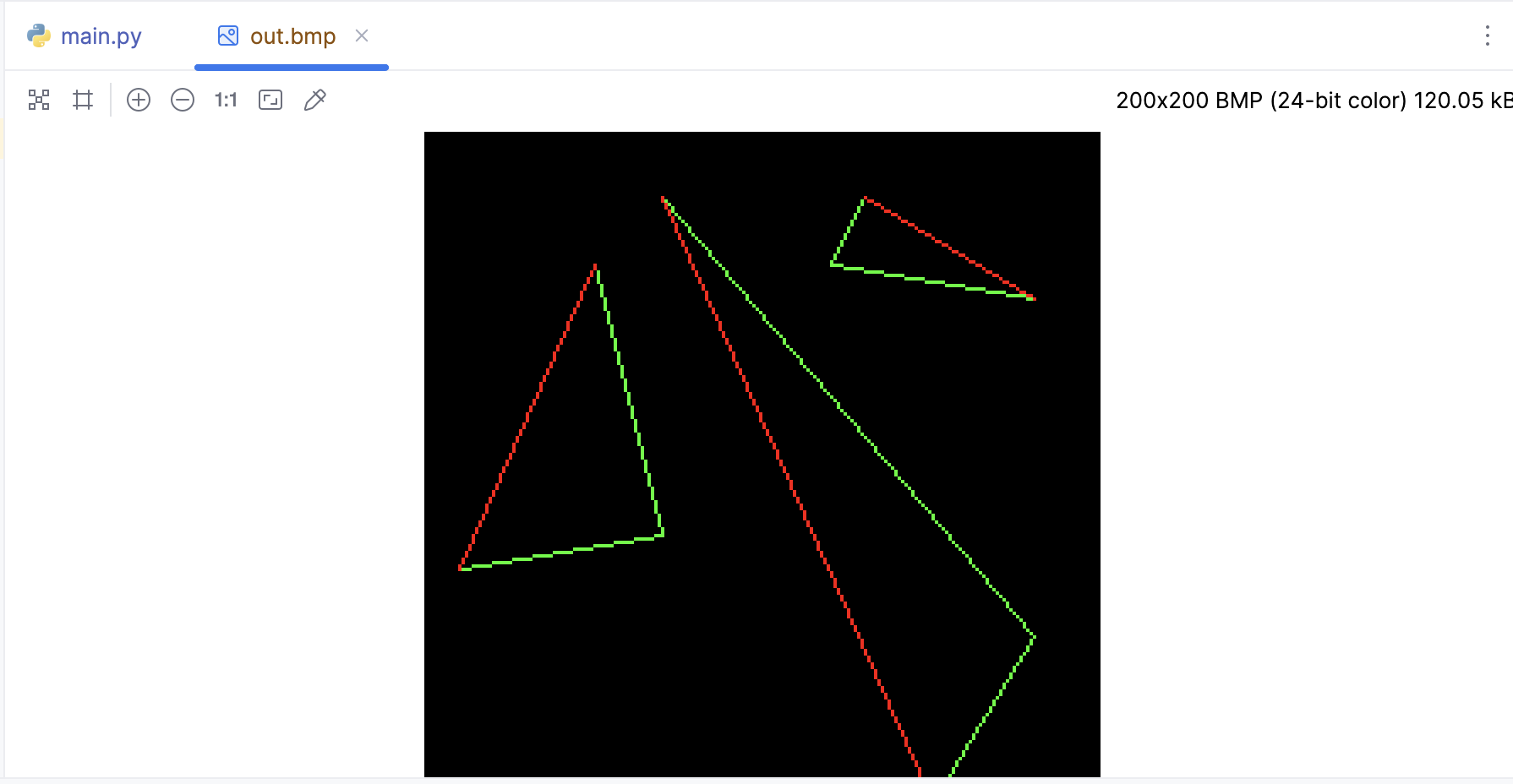
三角形通过水平切割线分成上下两部分,这样的话就可以通过水平扫线的方式的填充这个三角形。先来绘制下半部分:
def triangle(p0: Vec2, p1: Vec2, p2: Vec2, img: MyImage):
    if p0.y > p1.y:
        p0, p1 = p1, p0
    if p0.y > p2.y:
        p0, p2 = p2, p0
    if p1.y > p2.y:
        p1, p2 = p2, p1
    line(p0.x, p0.y, p1.x, p1.y, img, green)
    line(p1.x, p1.y, p2.x, p2.y, img, green)
    line(p2.x, p2.y, p0.x, p0.y, img, red)
    # 绘制下半部分
    # 计算线段的斜率
    slope0 = (p1.x - p0.x) / (p1.y - p0.y) if p1.y != p0.y else 0
    slope1 = (p2.x - p0.x) / (p2.y - p0.y) if p2.y != p0.y else 0
    # 从底部开始绘制
    for y in range(int(p0.y), int(p1.y) + 1):
        xs = p0.x + slope0 * (y - p0.y)  # 计算扫描线的起始点
        xe = p0.x + slope1 * (y - p0.y)  # 计算扫描线的结束点
        # 确保 xs < xe
        if xs > xe:
            xs, xe = xe, xs
        # 绘制水平线
        for x in range(int(xs), int(xe)):
            img.putpixel((x, y), green)
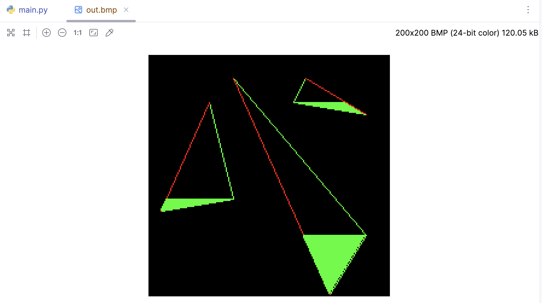
现在把上半部分也补上:
white = (255, 255, 255)
red = (255, 0, 0)
green = (0, 255, 0)


def triangle(p0: Vec2, p1: Vec2, p2: Vec2, img: MyImage):
    if p0.y > p1.y:
        p0, p1 = p1, p0
    if p0.y > p2.y:
        p0, p2 = p2, p0
    if p1.y > p2.y:
        p1, p2 = p2, p1
    # line(p0.x, p0.y, p1.x, p1.y, img, green)
    # line(p1.x, p1.y, p2.x, p2.y, img, green)
    # line(p2.x, p2.y, p0.x, p0.y, img, red)
    # 绘制下半部分
    # 计算线段的斜率
    slope0 = (p1.x - p0.x) / (p1.y - p0.y) if p1.y != p0.y else 0
    slope1 = (p2.x - p0.x) / (p2.y - p0.y) if p2.y != p0.y else 0
    # 从底部开始绘制
    for y in range(int(p0.y), int(p1.y) + 1):
        xs = p0.x + slope0 * (y - p0.y)  # 计算扫描线的起始点
        xe = p0.x + slope1 * (y - p0.y)  # 计算扫描线的结束点
        # 确保 xs < xe
        if xs > xe:
            xs, xe = xe, xs
        # 绘制水平线
        for x in range(int(xs), int(xe)):
            img.putpixel((x, y), green)
    # 绘制上半部分
    slope2 = (p2.x - p1.x) / (p2.y - p1.y) if p2.y != p1.y else 0
    for y in range(int(p1.y), int(p2.y)):
        xs = p1.x + slope2 * (y - p1.y)  # 计算扫描线的起始点
        xe = p0.x + slope1 * (y - p0.y)  # 计算扫描线的结束点

        # 确保 xs < xe
        if xs > xe:
            xs, xe = xe, xs

        # 绘制水平线
        for x in range(int(xs), int(xe)):
            img.putpixel((x, y), red)
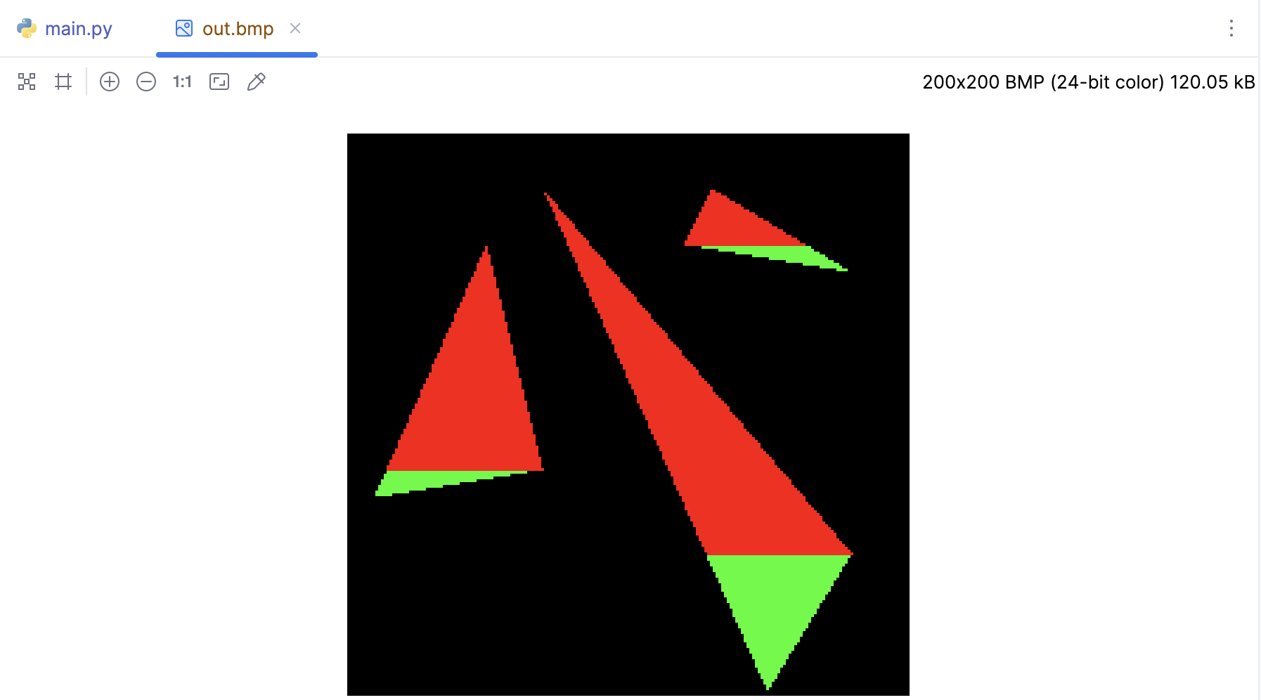
我们可以将这两个循环合并为一个,通过在循环中更改斜率和范围来处理上下两部分。在循环中,我们检查y是否小于p1.y,如果是,我们就在下半部分,否则我们就在上半部分。然后我们根据这个信息计算扫描线的起始点。
def triangle(p0: Vec2, p1: Vec2, p2: Vec2, img: MyImage):
    if p0.y > p1.y:
        p0, p1 = p1, p0
    if p0.y > p2.y:
        p0, p2 = p2, p0
    if p1.y > p2.y:
        p1, p2 = p2, p1
    # 计算线段的斜率
    slope0 = (p1.x - p0.x) / (p1.y - p0.y) if p1.y != p0.y else 0
    slope1 = (p2.x - p0.x) / (p2.y - p0.y) if p2.y != p0.y else 0
    slope2 = (p2.x - p1.x) / (p2.y - p1.y) if p2.y != p1.y else 0

    # 从底部开始绘制
    for y in range(int(p0.y), int(p2.y)):
        if y < p1.y:  # 如果在下半部分
            xs = p0.x + slope0 * (y - p0.y)  # 计算扫描线的起始点
        else:  # 如果在上半部分
            xs = p1.x + slope2 * (y - p1.y)  # 计算扫描线的起始点
        xe = p0.x + slope1 * (y - p0.y)  # 计算扫描线的结束点

        # 确保 xs < xe
        if xs > xe:
            xs, xe = xe, xs

        # 绘制水平线
        for x in range(int(xs), int(xe)):
            img.putpixel((x, y), green)
当然我们也可以用Tinyrenderer中计算插值的方式来完成,使用alpha和beta两个变量来计算扫描线的起始点和结束点。alpha是用于计算从t0到t2的插值,beta是用于计算从t0到t1或从t1到t2的插值,具体取决于是否在三角形的下半部分或上半部分。
def triangle(p0: Vec2, p1: Vec2, p2: Vec2, img: MyImage):
    # 如果点的纵坐标不是按升序排序的,则交换它们
    if p0.y > p1.y:
        p0, p1 = p1, p0
    if p0.y > p2.y:
        p0, p2 = p2, p0
    if p1.y > p2.y:
        p1, p2 = p2, p1

    total_height = p2.y - p0.y
    if total_height == 0:  # 如果三个点在同一水平线上,直接返回
        return

    for i in range(total_height):
        second_half = i > p1.y - p0.y or p1.y == p0.y
        segment_height = p2.y - p1.y if second_half else p1.y - p0.y
        if segment_height == 0:  # 如果上半部分或下半部分的高度为0,跳过这一次循环
            continue
        alpha = i / total_height
        beta = (i - (p1.y - p0.y if second_half else 0)) / segment_height
        A = p0 + (p2 - p0) * alpha
        B = p1 + (p2 - p1) * beta if second_half else p0 + (p1 - p0) * beta

        # 确保 A.x < B.x
        if A.x > B.x:
            A, B = B, A

        # 绘制水平线
        for x in range(int(A.x), int(B.x)):
            img.putpixel((x, p0.y + i), green)
扫线的方式确实可行,但是扫线是一种专为单线程 CPU 编程而设计的古老方法,效率相对较低。
包围盒算法
包围盒算法是一种简单有效的用于绘制三角形的方法,下面我们用包围盒的方式来完成三角形的绘制,我们首先计算出三角形的包围盒,也就是包含三角形的最小矩形。然后,我们遍历包围盒中的每个像素,对于每个像素,我们计算它到三角形三个顶点的向量,然后计算这些向量的叉积。如果所有的叉积都是正的,那么这个像素就在三角形内,我们就将其颜色设为绿色。
让我们看一下下面的伪代码:
function DrawTriangle(p0, p1, p2, img):
    // 计算三角形的包围盒
    minX = max(0, floor(min(p0.x, p1.x, p2.x)))
    maxX = min(img.width - 1, ceil(max(p0.x, p1.x, p2.x)))
    minY = max(0, floor(min(p0.y, p1.y, p2.y)))
    maxY = min(img.height - 1, ceil(max(p0.y, p1.y, p2.y)))

    // 遍历包围盒中的每个像素
    for x from minX to maxX:
        for y from minY to maxY:
            // 计算像素点到三角形三个顶点的向量
            v0 = p0 - Vec2(x, y)
            v1 = p1 - Vec2(x, y)
            v2 = p2 - Vec2(x, y)

            // 计算向量的叉积,以判断像素点是否在三角形内
            cross0 = v0.cross(v1)
            cross1 = v1.cross(v2)
            cross2 = v2.cross(v0)

            // 如果像素点在三角形内,就将其颜色设为绿色
            if cross0 >= 0 and cross1 >= 0 and cross2 >= 0:
                img.set_pixel(x, y, green)
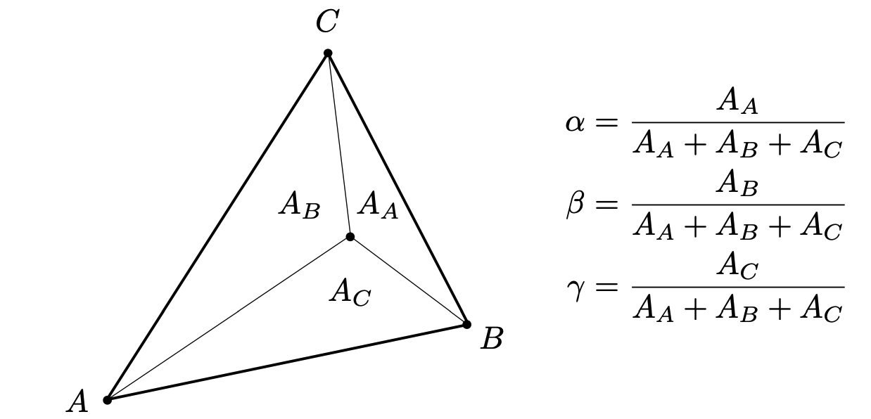
这个伪代码只适用于顶点按逆时针顺序给出的三角形。如果顶点是按顺时针顺序给出的,那么我们需要改变叉积的判断条件,将>=改为<=。其实我们完全有更简单的方式来解决这个问题,那就是重心坐标。给定一个包含点 A、B、C 和点 P 的三角形,我们想要找到一个向量 u、v、w,使得:
$$ P = u A + v B + w C $$
换句话说, (u, v, w) 是 P 关于三角形 ABC 的重心坐标。它们满足:u + v + w = 1,u、v 、w均在0-1之间。如果点P位于三角形内部,那么u、v 、w 都大于0,如果位于三角形外部,则至少有一个小于0。可以参考下图:
重心坐标这种方式是一种描述三角形内点的位置的方式,它将每个点表示为三角形顶点的加权平均值。如果一个点的重心坐标坐标的所有分量都大于等于0,那么这个点就在三角形内。这种方法的优点是,它可以直接处理任意形状的三角形,无需担心三角形是顺时针还是逆时针排列的,也无需担心三角形的顶点是否按照特定的顺序排列。
def triangle_area_2d(a: Vec2, b: Vec2, c: Vec2) -> float:
    """
    计算三角形面积
    """
    return .5 * ((b.y - a.y) * (b.x + a.x) + (c.y - b.y) * (c.x + b.x) + (a.y - c.y) * (a.x + c.x))


def barycentric(A, B, C, P):
    """
    计算重心坐标 u, v, w
    """
    total_area = triangle_area_2d(A, B, C)
    u = triangle_area_2d(P, B, C) / total_area
    v = triangle_area_2d(P, C, A) / total_area
    w = triangle_area_2d(P, A, B) / total_area
    return Vec3([u, v, w])


def triangle(p0: Vec2, p1: Vec2, p2: Vec2, img: MyImage):
    min_x = max(0, min(p0.x, p1.x, p2.x))
    max_x = min(img.width - 1, max(p0.x, p1.x, p2.x))
    min_y = max(0, min(p0.y, p1.y, p2.y))
    max_y = min(img.height - 1, max(p0.y, p1.y, p2.y))
    P = Vec2((0, 0))
    # 遍历包围盒内的每个像素
    for P.y in range(min_y, max_y+1):
        for P.x in range(min_x, max_x+1):
            # 计算当前像素的重心坐标
            bc_screen = barycentric(p0, p1, p2, P)
            # 如果像素的重心坐标的任何一个分量小于0,那么这个像素就在三角形的外部,我们就跳过它
            if bc_screen.x < 0 or bc_screen.y < 0 or bc_screen.z < 0:
                continue
            image.putpixel((P.x, P.y), red)
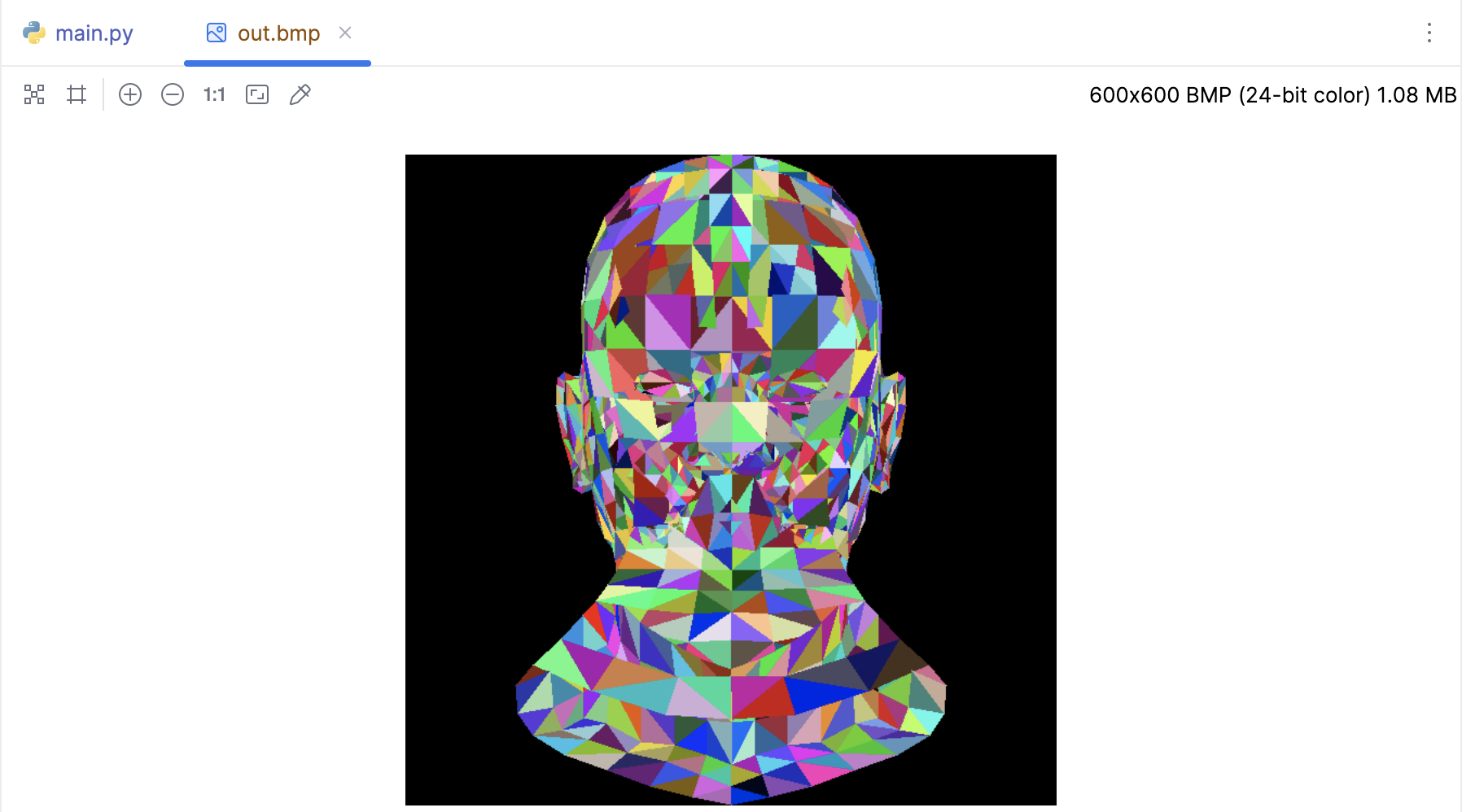
加载模型并随机着色
我们已经知道如何用空三角形绘制模型。 让我们用随机颜色填充它们。下面的代码有助于我们看到代码是如何填充三角形的:
if __name__ == '__main__':
    width = 600
    height = 600
    image = MyImage((width, height))

    obj = OBJFile('african_head.obj')
    obj.parse()

    def random_color():
        return random.randint(0, 255), random.randint(0, 255), random.randint(0, 255)

    for face in obj.faces:
        screen_coords = []
        for j in range(3):
            v: Vec3 = obj.vert(face[j])
            screen_coords.append(Vec2([int((v.x + 1) * width / 2), int((v.y + 1) * height / 2)]))
        triangle(screen_coords[0], screen_coords[1], screen_coords[2], image, random_color())
    image.save('out.bmp')
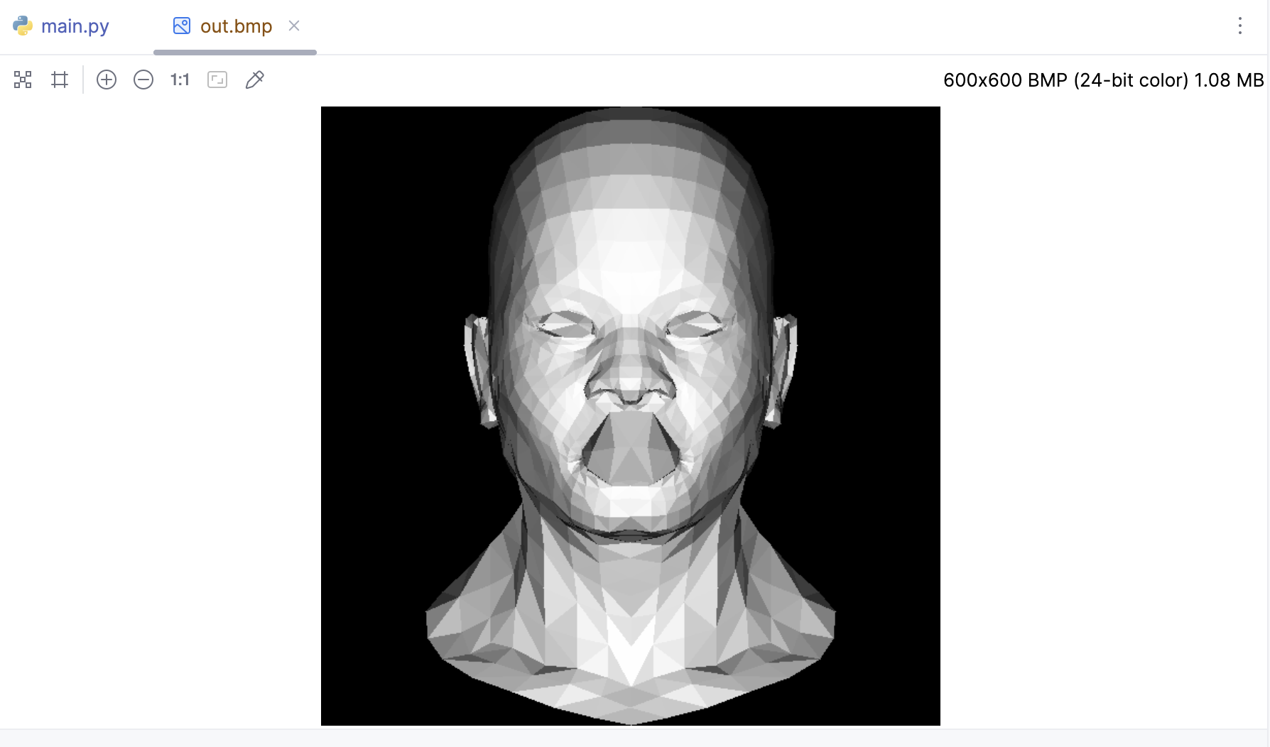
背面剔除与光照模型
在强度相同的光照下,与光线方向垂直的多边形面会被照得更亮。我们通过冯氏光照模型很容易得出这样的结论 :当多边形与光线平行时,接收的光照是 0。其实照明强度等于光向量与给定三角形法线向量的点积,三角形的法线,可以通过三角形两条边做叉积得到。
if __name__ == '__main__':
    width = 600
    height = 600
    image = MyImage((width, height))

    obj = OBJFile('african_head.obj')
    obj.parse()

    light_dir = Vec3([0, 0, -1])
    for face in obj.faces:
        screen_coords = []
        world_coords = [None, None, None]
        for j in range(3):
            v: Vec3 = obj.vert(face[j])
            screen_coords.append(Vec2([int((v.x + 1) * width / 2), int((v.y + 1) * height / 2)]))
            world_coords[j] = v
        # 计算三角形的法向量和光照强度
        n: Vec3 = (world_coords[2] - world_coords[0]).cross(world_coords[1] - world_coords[0])
        n.normalize()
        intensity = n * light_dir
        # 负的就剔除掉
        if intensity > 0:
            triangle(screen_coords[0], screen_coords[1], screen_coords[2], image,
                     (int(255 * intensity), int(255 * intensity), int(255 * intensity)))

    image.save('out.bmp')
Gamma 矫正
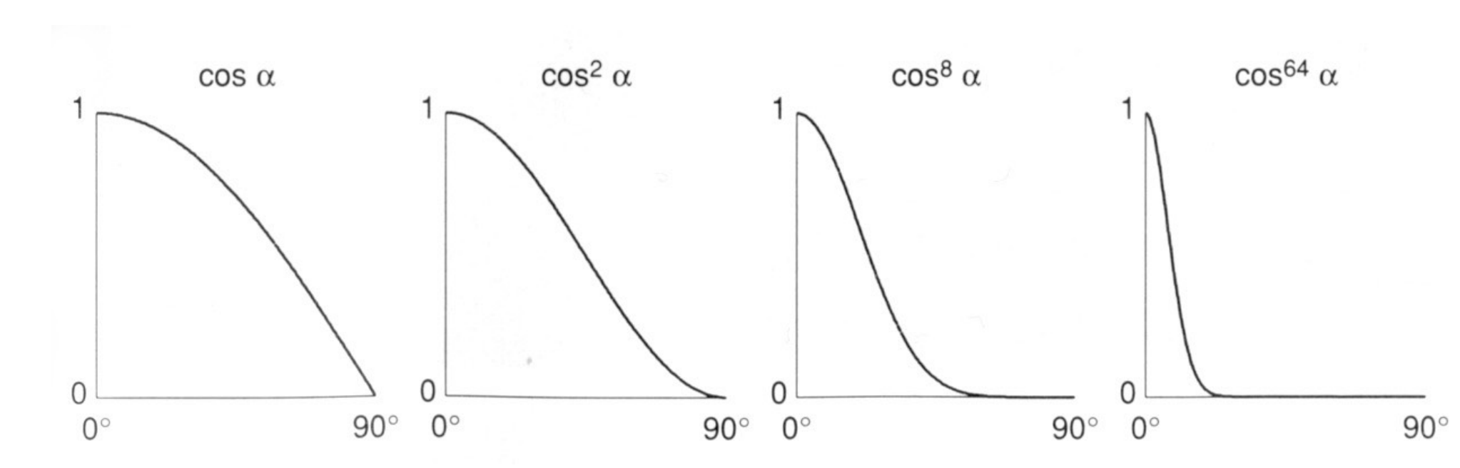
注意,在TinyRenderer中会把颜色的计算视为线性的,然而实际上 (128, 128, 128) 还没有 (255, 255, 255) 一半亮。也就是说,我们忽略 gamma 矫正,并容忍颜色亮度的误差。正常情况下会做一些次方倍率以接近真实情况,比如:
因为Gamma 校正的本质就是就是对图像进行非线性变换,使得图像在人眼看来更接近原始场景。这是因为人眼对亮度的感知是非线性的,我们对暗区域的变化更敏感,对亮区域的变化则不太敏感。通过 Gamma 矫正,我们可以更好地调整图像的暗区和亮区,使其更符合人眼的观察习惯。Gamma 矫正的数学公式通常表示为:
$$ O = I^\gamma $$
其中,O 是输出图像,I 是输入图像,$ \gamma $ 是 Gamma 值。如果 $\gamma < 1$,则会增强图像的暗区,使图像看起来更亮;如果 $\gamma > 1$,则会压暗图像的亮区,使图像看起来更暗。
只有当 intensity 大于0时才会进行 Gamma 矫正,否则直接跳过,就不会产生复数了。
if __name__ == '__main__':
    width = 400
    height = 400
    image = MyImage((width, height))

    obj = OBJFile('african_head.obj')
    obj.parse()

    light_dir = Vec3([0, 0, -1])
    gamma = 2.2  # Gamma 值
    for face in obj.faces:
        screen_coords = []
        world_coords = [None, None, None]
        for j in range(3):
            v: Vec3 = obj.vert(face[j])
            screen_coords.append(Vec2([int((v.x + 1) * width / 2), int((v.y + 1) * height / 2)]))
            world_coords[j] = v
        # 计算三角形的法向量和光照强度
        n: Vec3 = (world_coords[2] - world_coords[0]).cross(world_coords[1] - world_coords[0])
        n.normalize()
        intensity = n * light_dir
        # 负的就剔除掉
        if intensity > 0:
            # 进行 Gamma 矫正
            intensity = intensity ** (1 / gamma)
            triangle(screen_coords[0], screen_coords[1], screen_coords[2], image,
                     (int(255 * intensity), int(255 * intensity), int(255 * intensity)))

    image.save('out2.bmp')
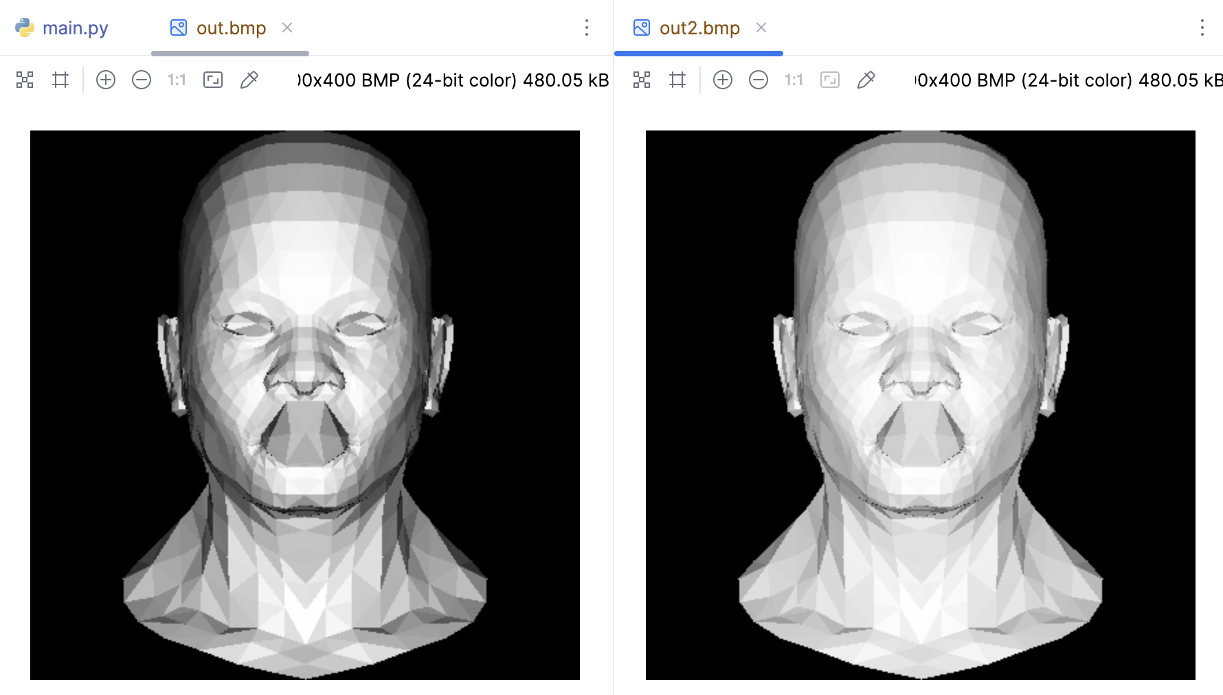
到目前为止,我们加载了模型,并且成功的做了背面剔除,并且添加了光照,而且跟对人眼特性做了Gamma 校正。但是此时嘴的内腔绘制在了嘴唇的顶部,这是因为我们现有的背面剔除方案仅适用于凸出的形状,在下个章节我们将通过 z-buffer 来解决掉这个问题。