PyTinyRenderer软渲染器-04
在之前的旅程中,我们已经成功地通过Z-Buffer算法已经很完美的处理了嘴唇凹进去的阴影面缺显示在上层的问题,并且把纹理贴在了模型上,达到了我们期望的基本效果。但是我们一直都是从正面视角去观察这个模型,既然是一个渲染引擎,当然也要能切换各个角度去渲染模型,所以本篇笔记的核心内容是理解和掌握透视投影的原理,以及如何利用坐标系变换的思想去推导视图变换矩阵,从而实现移动相机从其他角度渲染模型。对了还有实战使用三种着色方法(Flat Shading、Gouraud Shading、Phong Shading)进行片元着色。
透视投影与正交投影
在之前有一篇笔记着重介绍了这部分 ——《M-V-P变换与透视投影矩阵的推导》,这篇是基于计算机图形学 (闫令琪老师)在GAMES101中的课程总结出的。M-V-P 变换是模型变换、视图变换和投影变换的结合,用于将三维空间中的内容显示到二维屏幕上。文中首先介绍了仿射变换,并解释了三维空间中缩放、平移和旋转等基本操作。接着详述了视图变换过程,即通过平移和旋转矩阵调整摄像机坐标系与世界坐标系重合。然后讨论了正交投影与透视投影的区别及其实现方式,特别强调透视投影近大远小的效果以及如何通过齐次坐标系统进行 “挤压” 操作来完成从透视到正交的映射。最后提出了经过模型、视图、投影和视口四个步骤后可以成功地将游戏世界内物体呈现在屏幕上,并总结这一流程并不复杂只要理清各步骤即可。
需要理解比较重要的几个概念:
线性变换、仿射变换、齐次坐标、透视投影、M-V-P变换,这个几个概念搞清楚了再看接下来的内容。我们先定义一个Matrix矩阵类,用于矩阵的常用操作,当然为了快捷直接使用了numpy:
import numpy as np


class Matrix:
    def __init__(self, r=4, c=4):
        self.m = np.zeros((r, c), dtype=float)
        self.rows = r
        self.cols = c

    @staticmethod
    def identity(dimensions):
        mat = Matrix(dimensions, dimensions)
        mat.m = np.eye(dimensions, dtype=float)
        return mat

    def __getitem__(self, i):
        assert 0 <= i < self.rows
        return self.m[i]

    def __mul__(self, a):
        assert self.cols == a.rows
        return Matrix.from_np(self.m @ a.m)

    def transpose(self):
        return Matrix.from_np(np.transpose(self.m))

    def inverse(self):
        assert self.rows == self.cols
        return Matrix.from_np(np.linalg.inv(self.m))

    @staticmethod
    def from_np(np_matrix):
        m = Matrix(np_matrix.shape[0], np_matrix.shape[1])
        m.m = np_matrix
        return m

    def __str__(self):
        return str(self.m)
下面开始进行透视投影变换的流程,因为暂时不做model、view变换,所以我们只是简单的返回一个单位矩阵即可。
# 摄像机摆放的位置
cameraPos = Vec3([0, 0, 3])


def local_2_homo(v: Vec3):
    """
    局部坐标变换成齐次坐标
    """
    m = Matrix(4, 1)
    m[0][0] = v.x
    m[1][0] = v.y
    m[2][0] = v.z
    m[3][0] = 1.0
    return m


# 模型变换矩阵
def model_matrix():
    return Matrix.identity(4)


# 视图变换矩阵
def view_matrix():
    return Matrix.identity(4)


# 透视投影变换矩阵
def projection_matrix():
    projection = Matrix.identity(4)
    projection[3][2] = -1.0 / cameraPos.z
    return projection


# 此时我们的所有的顶点已经经过了透视投影变换,接下来需要进行透视除法
def projection_division(m: Matrix):
    m[0][0] = m[0][0] / m[3][0]
    m[1][0] = m[1][0] / m[3][0]
    m[2][0] = m[2][0] / m[3][0]
    m[3][0] = 1.0
    return m


def viewport_matrix(x, y, w, h, depth):
    """
    视口变换将NDC坐标转换为屏幕坐标
    """
    m = Matrix.identity(4)
    m[0][3] = x + w / 2.
    m[1][3] = y + h / 2.
    m[2][3] = depth / 2.

    m[0][0] = w / 2.
    m[1][1] = h / 2.
    m[2][2] = depth / 2.
    return m


def homo_2_vertices(m: Matrix):
  	"""
  	去掉第四个分量,将其恢复到三维坐标
  	"""
    return Vec3([int(m[0][0]), int(m[1][0]), int(m[2][0])])


if __name__ == '__main__':
    width = 600
    height = 600
    depth = 255

    tga: Image = Image.open('african_head_diffuse.tga')

    image = MyImage((width, height))

    # -sys.maxsize - 1 最小值
    z_buffer = [-sys.maxsize - 1] * width * height

    obj = OBJFile('african_head.obj')
    obj.parse()

    model_ = model_matrix()
    view_ = view_matrix()
    projection_ = projection_matrix()
    viewport_ = viewport_matrix(width / 8, height / 8, width * 3 / 4, height * 3 / 4, depth)

    light_dir = Vec3([0, 0, -1])
    gamma = 2.2
    for face in obj.faces:
        screen_coords = [None, None, None]  # 第i个面片三个顶点的屏幕坐标
        world_coords = [None, None, None]  # 第i个面片三个顶点的世界坐标
        uv_coords = [None, None, None]
        for j in range(3):
            v: Vec3 = obj.vert(face[j][0])
            world_coords[j] = v
            uv_coords[j] = obj.texcoord(face[j][1])  # 获取纹理坐标

            screen_coords[j] = homo_2_vertices(viewport_ * projection_division(
                projection_ * view_ * model_ * local_2_homo(v)))

        # 计算三角形的法向量和光照强度
        n: Vec3 = (world_coords[2] - world_coords[0]).cross(world_coords[1] - world_coords[0])
        n.normalize()
        intensity = n * light_dir
        # 负的就剔除掉
        if intensity > 0:
            intensity = intensity ** (1 / gamma)
            triangle(screen_coords[0], screen_coords[1], screen_coords[2],
                     uv_coords[0], uv_coords[1], uv_coords[2],
                     intensity, image, tga)

    image.save('out.bmp')
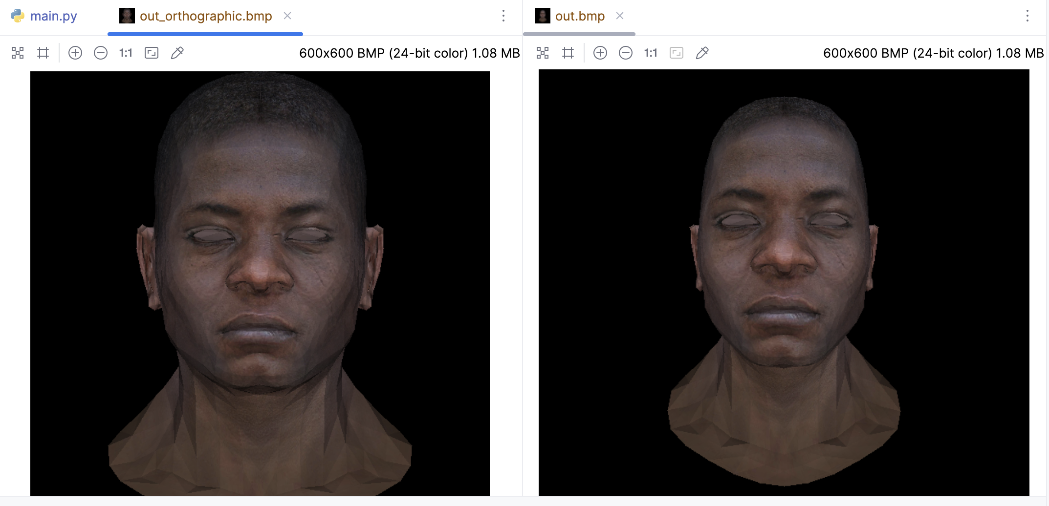
对比正交投影(左侧)和透视投影(右侧)不难发现,透视投影的渲染结果更具有真实感:
坐标系变换推导
其实核心就是就是我们要理解坐标系变换,即如何在两个不同的坐标系之间转换点的坐标。这在计算机图形学中是一个重要的概念,因为我们经常需要在世界坐标系、视图坐标系、物体坐标系等之间进行转换。
首先在欧几里得空间中,坐标可以由一个点(原点)和一组基向量给出。如果点P在坐标系(O, i, j, k)中的坐标为(x, y, z),那么向量OP可以表示为:
$$\vec{OP} = x\vec{i} + y\vec{j} + z\vec{k}$$
然后,假设我们有另一个坐标系(O’, i’, j’, k’)。我们如何将一个坐标系中的坐标转换到另一个坐标系呢?首先,由于(i, j, k)和(i’, j’, k’)都是3D空间的基,存在一个逆矩阵M,使得:
$$\begin{bmatrix} \vec{i’} \\ \vec{j’} \\ \vec{k’} \end{bmatrix} = M \begin{bmatrix} \vec{i} \\ \vec{j} \\ \vec{k} \end{bmatrix}$$
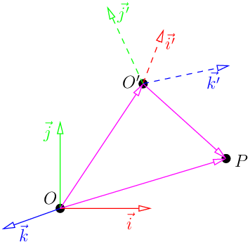
然后,我们重新表示向量OP:
$$\overrightarrow{OP}=\overrightarrow{OO’}+\overrightarrow{O’P}=\begin{bmatrix}\vec{i}&\vec{j}&\vec{k}\end{bmatrix}\begin{bmatrix}O’_x\\O’_y\\O’_z\end{bmatrix}+\begin{bmatrix}\vec{i’}&\vec{j’}&\vec{k’}\end{bmatrix}\begin{bmatrix}x’\\y’\\z’\end{bmatrix}$$
现在,我们用基变换矩阵替换右侧的(i’, j’, k’):
$$\overrightarrow{OP}=\begin{bmatrix}\vec{i}&\vec{j}&\vec{k}\end{bmatrix}\left(\begin{bmatrix}O_x’\\O_y’\\O_z’\end{bmatrix}+M\begin{bmatrix}x’\\y’\\z’\end{bmatrix}\right)$$
这就给出了从一个坐标系到另一个坐标系的坐标变换公式,我们经常需要在不同的坐标系之间转换坐标。
$$\begin{bmatrix}x\\y\\z\end{bmatrix}=\begin{bmatrix}O’_x\\O’_y\\O’_z\end{bmatrix}+M\begin{bmatrix}x’\\y’\\z’\end{bmatrix}\quad\Rightarrow\quad\begin{bmatrix}x’\\y’\\z’\end{bmatrix}=M^{-1}\left(\begin{bmatrix}x\\y\\z\end{bmatrix}-\begin{bmatrix}O’_x\\O’_y\\O’_z\end{bmatrix}\right)$$
所以结论就是:对坐标轴进行M变换,实际上相当于对坐标进行M的逆变换。
在《M-V-P变换与透视投影矩阵的推导》这篇笔记中,其实阅读视图变换 (view transformation)这部一部分的内容,我们很容易推断出视图变换矩阵。总结来看就是两个步骤:将相机位置移动至原点以及通过旋转矩阵将二者坐标系重合。
我们可以这样理解,如果要在世界坐标系下的 (x、y、z) 位置设置相机,那么我们把相机再移回世界坐标系原点的位移就是(-x、-y、-z)。所以我们当以相机为坐标原点的时候,所有在原来坐标系下的物体都要加上这个负的平移分量。那么这个平移矩阵如下:
$$\begin{bmatrix}1&0&0&-x\\0&1&0&-y\\0&0&1&-z\\0&0&0&1\end{bmatrix}$$
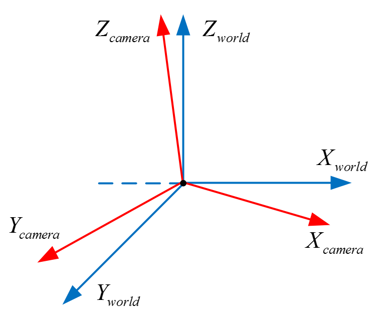
我们将原来的坐标系转变成相机坐标系,不仅需要平移到相机位置,还要旋转到相机的朝向。我们要将蓝色的坐标系通过旋转变换成红色的相机坐标系。由于坐标系的三个基向量都是单位化的,所以最简单的办法就是点乘,做法就是点乘相机坐标系的三个基向量:
$$\begin{bmatrix}U_x&U_y&U_z&0\\V_x&V_y&V_z&0\\N_x&N_y&N_z&0\\0&0&0&1\end{bmatrix}\begin{bmatrix}x_{world}\\y_{world}\\z_{world}\\1\end{bmatrix}=\begin{bmatrix}x_{camera}\\y_{camera}\\z_{camera}\\1\end{bmatrix}$$
其中 V 指向相机坐标系的 y 轴,U 指向相机坐标系的 x 轴,N 指向相机坐标系的 z 轴。这两个矩阵就组成了视图变换矩阵:
$$\begin{bmatrix}r_{x}&r_{y}&r_{z}&-e\cdot r\\u_{x}&u_{y}&u_{z}&-e\cdot u\\v_{x}&v_{y}&v_{z}&-e\cdot v\\0&0&0&1\end{bmatrix}$$
移动相机代码实现
定义Camera类表示相机:
from vector import Vec3


class Camera:
    def __init__(self, eye_p: Vec3 = Vec3([0, 0, 0]),
                 world_up: Vec3 = Vec3([0, 1, 0]),
                 front: Vec3 = Vec3([0, 0, -1])):
        self.position = eye_p
        self.word_up = world_up
        self.front = front.normalize()
        self.right = self.front.cross(self.word_up).normalize()
        self.up = self.right.cross(self.front).normalize()
这里的成员变量分别对应:
position:即相机在世界坐标系中的位置;
world_up:我们的辅助向量,一般设置为(0, 1, 0),即Y轴的正向朝向;
front:对应我们之前推导的v轴的反方向,u轴的方向是从c——>e,即从观察点指向相机中心,但是我们一般常说相机的朝向总是认为是从相机位置指向观察点的,即e——–>c
right:对应我们之前推导的r轴的方向;
up,对应我们之前推导的u轴的方向;
这里还需要在Vec3中加入get获得x、y、z的方法:
  def get(self, i):
      if i == 0:
          return self.x
      elif i == 1:
          return self.y
      elif i == 2:
          return self.z
在上面的透视投影中,视图变换矩阵 view_matrix给的一个单位矩阵,现在只需要使用真实的视图变换矩阵即可,其它代码不用变化:
def view_matrix(camera: Camera):
    r_inverse = np.identity(4)
    t_inverse = np.identity(4)
    for i in range(3):
        r_inverse[0][i] = camera.right.get(i)
        r_inverse[1][i] = camera.up.get(i)
        r_inverse[2][i] = -camera.front.get(i)

        t_inverse[i][3] = -camera.position.get(i)
    view = np.dot(r_inverse, t_inverse)
    return Matrix.from_np(view)
下面给出完整代码:
import sys

import numpy as np
from PIL import Image

from camera import Camera
from image import MyImage
from matrix import Matrix
from obj import OBJFile
from vector import Vec3, Vec2

white = (255, 255, 255)
red = (255, 0, 0)
green = (0, 255, 0)
blue = (0, 0, 255)


def triangle_area_2d(a: Vec2, b: Vec2, c: Vec2) -> float:
    """
    计算三角形面积
    """
    return .5 * ((b.y - a.y) * (b.x + a.x) + (c.y - b.y) * (c.x + b.x) + (a.y - c.y) * (a.x + c.x))


def barycentric(A, B, C, P):
    """
    计算重心坐标 u, v, w
    """
    total_area = triangle_area_2d(A, B, C)
    if total_area == 0:
        return None  # 或者抛出一个异常,或者返回一个特殊的值
    u = triangle_area_2d(P, B, C) / total_area
    v = triangle_area_2d(P, C, A) / total_area
    w = triangle_area_2d(P, A, B) / total_area
    return Vec3([u, v, w])


def triangle(p0: Vec3, p1: Vec3, p2: Vec3,
             uv0: Vec2, uv1: Vec2, uv2: Vec2,
             intensity, img: MyImage, tga: Image):
    min_x = max(0, min(p0.x, p1.x, p2.x))
    max_x = min(img.width - 1, max(p0.x, p1.x, p2.x))
    min_y = max(0, min(p0.y, p1.y, p2.y))
    max_y = min(img.height - 1, max(p0.y, p1.y, p2.y))
    P = Vec2((0, 0))

    # 遍历包围盒内的每个像素
    for P.y in range(min_y, max_y + 1):
        for P.x in range(min_x, max_x + 1):
            # 计算当前像素的重心坐标
            bc_screen = barycentric(p0, p1, p2, P)
            if bc_screen is None:
                continue
            # 如果像素的重心坐标的任何一个分量小于0,那么这个像素就在三角形的外部,我们就跳过它
            if bc_screen.x < 0 or bc_screen.y < 0 or bc_screen.z < 0:
                continue

            # 使用重心坐标来插值纹理坐标
            uv = uv0 * bc_screen.x + uv1 * bc_screen.y + uv2 * bc_screen.z
            # 使用插值后的纹理坐标来从TGA文件中获取颜色
            # 此TGA文件是从左上角开始的,所以需要将纵坐标反转
            color = tga.getpixel((int(uv.x * tga.width), tga.height - 1 - int(uv.y * tga.height)))
            color = (int(color[0] * intensity), int(color[1] * intensity), int(color[2] * intensity))

            # 计算当前像素的深度
            z = p0.z * bc_screen.x + p1.z * bc_screen.y + p2.z * bc_screen.z

            # 检查Z缓冲区,如果当前像素的深度比Z缓冲区中的值更近,那么就更新Z缓冲区的值,并绘制像素
            idx = P.x + P.y * img.width
            if z_buffer[idx] < z:
                z_buffer[idx] = z
                image.putpixel((P.x, P.y), color)


# 摄像机摆放的位置
eye_position = Vec3([1, 1, 3])
center = Vec3([0, 0, 0])

camera = Camera(eye_position, Vec3([0, 1, 0]), center - eye_position)

def local_2_homo(v: Vec3):
    """
    局部坐标变换成齐次坐标
    """
    m = Matrix(4, 1)
    m[0][0] = v.x
    m[1][0] = v.y
    m[2][0] = v.z
    m[3][0] = 1.0
    return m


# 模型变换矩阵
def model_matrix():
    return Matrix.identity(4)

# 视图变换矩阵
def view_matrix(camera: Camera):
    r_inverse = np.identity(4)
    t_inverse = np.identity(4)
    for i in range(3):
        r_inverse[0][i] = camera.right.get(i)
        r_inverse[1][i] = camera.up.get(i)
        r_inverse[2][i] = -camera.front.get(i)

        t_inverse[i][3] = -camera.position.get(i)
    view = np.dot(r_inverse, t_inverse)
    return Matrix.from_np(view)


# 透视投影变换矩阵
def projection_matrix():
    projection = Matrix.identity(4)
    projection[3][2] = -1.0 / eye_position.z
    return projection


# 此时我们的所有的顶点已经经过了透视投影变换,接下来需要进行透视除法
def projection_division(m: Matrix):
    m[0][0] = m[0][0] / m[3][0]
    m[1][0] = m[1][0] / m[3][0]
    m[2][0] = m[2][0] / m[3][0]
    m[3][0] = 1.0
    return m


def viewport_matrix(x, y, w, h, depth):
    """
    视口变换将NDC坐标转换为屏幕坐标
    """
    m = Matrix.identity(4)
    m[0][3] = x + w / 2.
    m[1][3] = y + h / 2.
    m[2][3] = depth / 2.

    m[0][0] = w / 2.
    m[1][1] = h / 2.
    m[2][2] = depth / 2.
    return m


def homo_2_vertices(m: Matrix):
    """
    去掉第四个分量,将其恢复到三维坐标
    """
    return Vec3([int(m[0][0]), int(m[1][0]), int(m[2][0])])


if __name__ == '__main__':
    width = 1600
    height = 1600
    depth = 255

    tga: Image = Image.open('african_head_diffuse.tga')

    image = MyImage((width, height))

    # -sys.maxsize - 1 最小值
    z_buffer = [-sys.maxsize - 1] * width * height

    obj = OBJFile('african_head.obj')
    obj.parse()

    model_ = model_matrix()
    view_ = view_matrix(camera)
    projection_ = projection_matrix()
    viewport_ = viewport_matrix(width / 8, height / 8, width * 3 / 4, height * 3 / 4, depth)

    light_dir = Vec3([0, 0, -1])
    gamma = 2.2
    for face in obj.faces:
        screen_coords = [None, None, None]  # 第i个面片三个顶点的屏幕坐标
        world_coords = [None, None, None]  # 第i个面片三个顶点的世界坐标
        uv_coords = [None, None, None]
        for j in range(3):
            v: Vec3 = obj.vert(face[j][0])
            world_coords[j] = v
            uv_coords[j] = obj.texcoord(face[j][1])  # 获取纹理坐标

            screen_coords[j] = homo_2_vertices(viewport_ * projection_division(
                projection_ * view_ * model_ * local_2_homo(v)))

        # 计算三角形的法向量和光照强度
        n: Vec3 = (world_coords[2] - world_coords[0]).cross(world_coords[1] - world_coords[0])
        n.normalize()
        intensity = n * light_dir
        # 负的就剔除掉
        if intensity > 0:
            intensity = intensity ** (1 / gamma)
            triangle(screen_coords[0], screen_coords[1], screen_coords[2],
                     uv_coords[0], uv_coords[1], uv_coords[2],
                     intensity, image, tga)

    image.save('out.bmp')
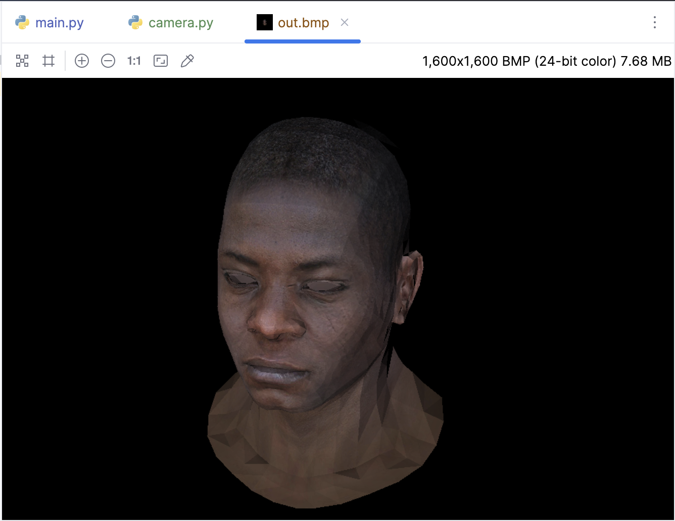
下面看看效果,我们已经成功通过把相机 “移动” 到侧面对模型进行了渲染:
三种着色方式
计算机图形学中,着色(Shading)是一个重要的概念,它决定了物体表面的颜色和亮度。常见以下三种:
Flat Shading:平面着色是最简单的着色技术。在这种技术中,每个多边形(通常是三角形)都被赋予一个单一的颜色。这个颜色通常是由多边形的法线向量和光源的方向决定的。因为每个多边形只有一个颜色,所以结果通常会显得非常“平坦”,没有渐变效果。这种技术的优点是计算简单,但缺点是视觉效果较差。
Gouraud Shading:高洛德着色是一种改进的着色技术。在这种技术中,每个顶点都被赋予一个颜色,然后在多边形内部进行插值,以产生渐变效果。这种技术的优点是可以产生较为平滑的视觉效果,但缺点是可能会出现“亮点”(即光源直接照射的地方)的渲染不准确。
Phong Shading:冯氏着色是一种更进一步的改进技术。在这种技术中,每个像素都被赋予一个颜色。颜色的计算是在每个像素位置进行的,而不是在顶点位置。然后,颜色会根据法线向量和光源的方向进行插值。这种技术的优点是可以产生非常平滑并且准确的视觉效果,特别是在渲染亮点方面。但是,这种技术的缺点是计算复杂度较高。
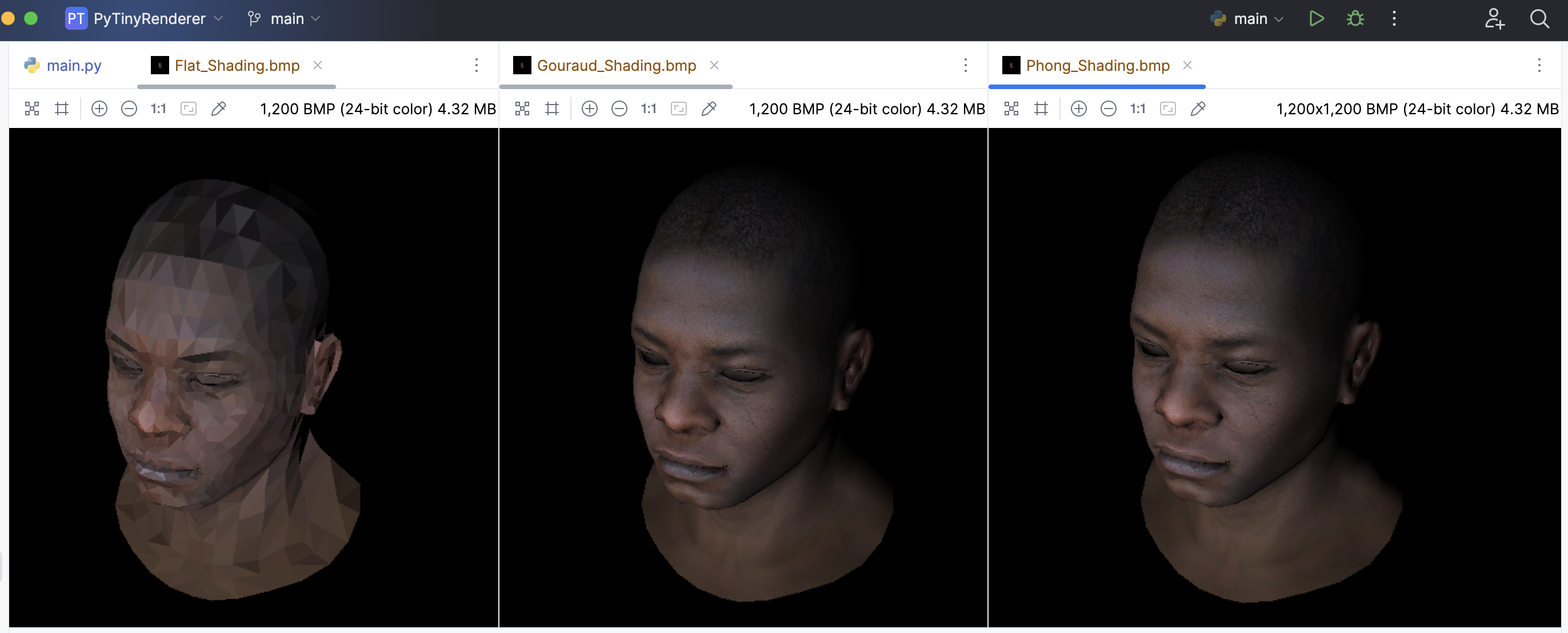
下面根据这三种着色方法,逐一进行对比:
Flat Shading
def triangle(p0: Vec3, p1: Vec3, p2: Vec3,
             uv0: Vec2, uv1: Vec2, uv2: Vec2,
             intensity, img: MyImage, tga: Image):
    min_x = max(0, min(p0.x, p1.x, p2.x))
    max_x = min(img.width - 1, max(p0.x, p1.x, p2.x))
    min_y = max(0, min(p0.y, p1.y, p2.y))
    max_y = min(img.height - 1, max(p0.y, p1.y, p2.y))
    P = Vec2((0, 0))

    # 计算三角形的颜色 Flat Shading
    uv = Vec3([(uv0 + uv1 + uv2).x/3, (uv0 + uv1 + uv2).y/3, (uv0 + uv1 + uv2).z/3])
    color = tga.getpixel((int(uv.x * tga.width), tga.height - 1 - int(uv.y * tga.height)))
    color = (int(color[0] * intensity), int(color[1] * intensity), int(color[2] * intensity))

    # 遍历包围盒内的每个像素
    for P.y in range(min_y, max_y + 1):
        for P.x in range(min_x, max_x + 1):
            # 计算当前像素的重心坐标
            bc_screen = barycentric(p0, p1, p2, P)
            if bc_screen is None:
                continue
            # 如果像素的重心坐标的任何一个分量小于0,那么这个像素就在三角形的外部,我们就跳过它
            if bc_screen.x < 0 or bc_screen.y < 0 or bc_screen.z < 0:
                continue

            # 计算当前像素的深度
            z = p0.z * bc_screen.x + p1.z * bc_screen.y + p2.z * bc_screen.z

            # 检查Z缓冲区,如果当前像素的深度比Z缓冲区中的值更近,那么就更新Z缓冲区的值,并绘制像素
            idx = P.x + P.y * img.width
            if z_buffer[idx] < z:
                z_buffer[idx] = z
                image.putpixel((P.x, P.y), color)
Gouraud Shading
因为需要用到定点法线,所以新增了normals,以及faces中存储了顶点法线的索引,obj.py 做如下改动:
from vector import Vec3


class OBJFile:
    def __init__(self, filename):
        self.filename = filename
        self.vertices = []
        self.normals = []  # 添加一个新的列表来存储法线
        self.texture_coords = []  # 添加一个新的列表来存储纹理坐标
        self.faces = []

    def parse(self):
        with open(self.filename, 'r') as file:
            for line in file:
                components = line.strip().split()
                if len(components) > 0:
                    if components[0] == 'v':
                        self.vertices.append([float(coord) for coord in components[1:]])
                    elif components[0] == 'vt':  # 添加一个新的条件来处理纹理坐标
                        self.texture_coords.append([float(coord) for coord in components[1:]])
                    elif components[0] == 'vn':  # 添加一个新的条件来处理法线
                        self.normals.append([float(coord) for coord in components[1:]])
                    elif components[0] == 'f':
                        # 修改这里,以便同时存储顶点、纹理坐标和法线的索引
                        self.faces.append([[int(index.split('/')[0]),
                                            int(index.split('/')[1]),
                                            int(index.split('/')[2])] for index in components[1:]])

    # 添加一个新的方法来获取法线
    def norm(self, index):
        return Vec3(self.normals[index - 1])

    def vert(self, i):
        """
        :param i: vertex index
        :param i: 因为obj文件的顶点索引是从1开始的,所以需要减1
        :return:
        """
        return Vec3(self.vertices[i - 1])

    def texcoord(self, i):  # 添加一个新的方法来获取纹理坐标
        """
        :param i: texture coordinate index
        :param i: 因为obj文件的纹理坐标索引是从1开始的,所以需要减1
        :return:
        """
        return Vec3(self.texture_coords[i - 1])
此时顶点法线信息有了,现在可以在三角形内部进行插值,以产生渐变效果:
def triangle(p0: Vec3, p1: Vec3, p2: Vec3,
             uv0: Vec2, uv1: Vec2, uv2: Vec2,
             intensity0, intensity1, intensity2,
             img: MyImage, tga: Image):
    min_x = max(0, min(p0.x, p1.x, p2.x))
    max_x = min(img.width - 1, max(p0.x, p1.x, p2.x))
    min_y = max(0, min(p0.y, p1.y, p2.y))
    max_y = min(img.height - 1, max(p0.y, p1.y, p2.y))
    P = Vec2((0, 0))

    # 遍历包围盒内的每个像素
    for P.y in range(min_y, max_y + 1):
        for P.x in range(min_x, max_x + 1):
            # 计算当前像素的重心坐标
            bc_screen = barycentric(p0, p1, p2, P)
            if bc_screen is None:
                continue
            # 如果像素的重心坐标的任何一个分量小于0,那么这个像素就在三角形的外部,我们就跳过它
            if bc_screen.x < 0 or bc_screen.y < 0 or bc_screen.z < 0:
                continue

            uv = uv0 * bc_screen.x + uv1 * bc_screen.y + uv2 * bc_screen.z
            color = tga.getpixel((int(uv.x * tga.width), tga.height - 1 - int(uv.y * tga.height)))

            # 插值光照强度
            intensity = intensity0 * bc_screen.x + intensity1 * bc_screen.y + intensity2 * bc_screen.z
            color = (int(color[0] * intensity), int(color[1] * intensity), int(color[2] * intensity))

            # 计算当前像素的深度
            z = p0.z * bc_screen.x + p1.z * bc_screen.y + p2.z * bc_screen.z

            # 检查Z缓冲区,如果当前像素的深度比Z缓冲区中的值更近,那么就更新Z缓冲区的值,并绘制像素
            idx = P.x + P.y * img.width
            if z_buffer[idx] < z:
                z_buffer[idx] = z
                image.putpixel((P.x, P.y), color)


# ... 其他相同代码省略

if __name__ == '__main__':
    width = 1200
    height = 1200
    depth = 255

    tga: Image = Image.open('african_head_diffuse.tga')

    image = MyImage((width, height))

    z_buffer = [-sys.maxsize - 1] * width * height

    obj = OBJFile('african_head.obj')
    obj.parse()

    model_ = model_matrix()
    view_ = view_matrix(camera)
    projection_ = projection_matrix()
    viewport_ = viewport_matrix(width / 8, height / 8, width * 3 / 4, height * 3 / 4, depth)

    light_dir = Vec3([0, 0, 1])
    gamma = 2.2
    for face in obj.faces:
        screen_coords = [None, None, None]  # 第i个面片三个顶点的屏幕坐标
        world_coords = [None, None, None]  # 第i个面片三个顶点的世界坐标
        uv_coords = [None, None, None]
        intensities = [0, 0, 0]
        for j in range(3):
            v: Vec3 = obj.vert(face[j][0])
            world_coords[j] = v
            uv_coords[j] = obj.texcoord(face[j][1])  # 获取纹理坐标

            screen_coords[j] = homo_2_vertices(viewport_ * projection_division(
                projection_ * view_ * model_ * local_2_homo(v)))

            n: Vec3 = obj.norm(face[j][2])  # 使用顶点法线
            n.normalize()
            intensities[j] = max(0, n * light_dir)
        triangle(screen_coords[0], screen_coords[1], screen_coords[2],
                     uv_coords[0], uv_coords[1], uv_coords[2],
                     intensities[0], intensities[1], intensities[2], image, tga)

    image.save('Gouraud_Shading.bmp')
Phong Shading
添加了三个新的参数 n0,n1 和 n2,这些参数是每个顶点的法线。然后我们在每个像素中插值这些法线,就像我们插值纹理坐标一样。最后使用插值后的法线来计算光照强度,并使用这个光照强度来调整像素的颜色。但是这个实现只考虑了漫反射光照,没有考虑环境光和镜面反射。如果要实现一个更完整的 Phong Shading,需要添加环境光和镜面反射的计算,这里暂时就不考虑了。
def triangle(p0: Vec3, p1: Vec3, p2: Vec3,
             uv0: Vec2, uv1: Vec2, uv2: Vec2,
             n0: Vec3, n1: Vec3, n2: Vec3,
             img: MyImage, tga: Image):
    min_x = max(0, min(p0.x, p1.x, p2.x))
    max_x = min(img.width - 1, max(p0.x, p1.x, p2.x))
    min_y = max(0, min(p0.y, p1.y, p2.y))
    max_y = min(img.height - 1, max(p0.y, p1.y, p2.y))
    P = Vec2((0, 0))

    # 遍历包围盒内的每个像素
    for P.y in range(min_y, max_y + 1):
        for P.x in range(min_x, max_x + 1):
            # 计算当前像素的重心坐标
            bc_screen = barycentric(p0, p1, p2, P)
            if bc_screen is None:
                continue
            # 如果像素的重心坐标的任何一个分量小于0,那么这个像素就在三角形的外部,我们就跳过它
            if bc_screen.x < 0 or bc_screen.y < 0 or bc_screen.z < 0:
                continue

            uv = uv0 * bc_screen.x + uv1 * bc_screen.y + uv2 * bc_screen.z
            color = tga.getpixel((int(uv.x * tga.width), tga.height - 1 - int(uv.y * tga.height)))

            # 插值法线
            n = n0 * bc_screen.x + n1 * bc_screen.y + n2 * bc_screen.z
            n.normalize()  # 正规化法线

            # 计算光照强度
            intensity = max(0, n * light_dir)
            color = (int(color[0] * intensity), int(color[1] * intensity), int(color[2] * intensity))

            z = p0.z * bc_screen.x + p1.z * bc_screen.y + p2.z * bc_screen.z
            # 检查Z缓冲区,如果当前像素的深度比Z缓冲区中的值更近,那么就更新Z缓冲区的值,并绘制像素
            idx = P.x + P.y * img.width
            if z_buffer[idx] < z:
                z_buffer[idx] = z
                image.putpixel((P.x, P.y), color)

# ... 其他相同代码省略

if __name__ == '__main__':
    width = 1200
    height = 1200
    depth = 255

    tga: Image = Image.open('african_head_diffuse.tga')

    image = MyImage((width, height))

    z_buffer = [-sys.maxsize - 1] * width * height

    obj = OBJFile('african_head.obj')
    obj.parse()

    model_ = model_matrix()
    view_ = view_matrix(camera)
    projection_ = projection_matrix()
    viewport_ = viewport_matrix(width / 8, height / 8, width * 3 / 4, height * 3 / 4, depth)

    light_dir = Vec3([0, 0, 1])
    gamma = 2.2
    for face in obj.faces:
        screen_coords = [None, None, None]  # 第i个面片三个顶点的屏幕坐标
        world_coords = [None, None, None]  # 第i个面片三个顶点的世界坐标
        uv_coords = [None, None, None]
        norms = [None, None, None]
        for j in range(3):
            v: Vec3 = obj.vert(face[j][0])
            world_coords[j] = v
            uv_coords[j] = obj.texcoord(face[j][1])  # 获取纹理坐标

            screen_coords[j] = homo_2_vertices(viewport_ * projection_division(
                projection_ * view_ * model_ * local_2_homo(v)))

            n: Vec3 = obj.norm(face[j][2])  # 使用顶点法线
            norms[j] = n
        triangle(screen_coords[0], screen_coords[1], screen_coords[2],
                     uv_coords[0], uv_coords[1], uv_coords[2],
                     norms[0], norms[1], norms[2], image, tga)

    image.save('Phong_Shading.bmp')
下面可以看看三种方式的对比:
本节就先这样,代码我放在这里了: https://github.com/zouchanglin/PyTinyRenderer